5292157-UIM-B-0317
4 Johnson Controls Unitary Products
SECTION III: UNIT INSTALLATION
UNIT SIZING
1. The size of the unit should be based on an acceptable heat loss or
gain calculation for the structure. The ACCA – Manual J or other
approved methods may be used. Reference Figure 4 and Table 1.
2. Only connect the air handler to a duct system which has an external
static pressure within the allowable range.
3. Airflow must be within the minimum and maximum limits approved
for electric heat, indoor coils and outdoor units.
Entering Air Temperature Limits
Wet °F Dry °F
4. When an air handler is installed so that supply ducts carry air circu-
lated by the air handler to areas outside the space containing the
air handler, the return air shall also be handled by duct(s) sealed to
the air handler casing and terminating in the space to be cooled/
heated.
5. Refer to the unit rating plate for the air handler model number, and
then see the dimensions page of this instruction for supply air ple-
num dimensions. The plenum must be installed according to the
instructions.
6. The installer must check available supply power and verify that it is
within the normal operating voltage range for the unit. The accept-
able voltage range for these units is as follows:
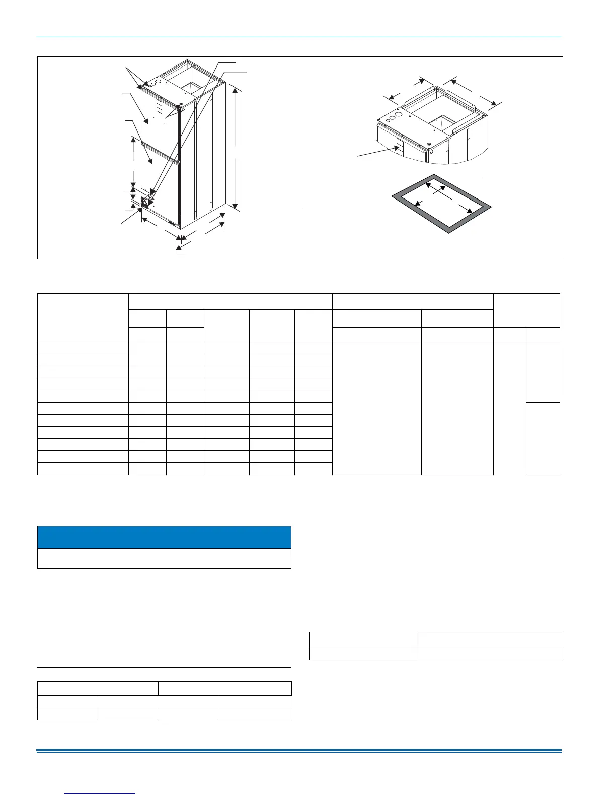
FIGURE 4: Dimensions & Duct Connection Dimensions
*
$
´
´
&
),/7(5$&&(66
'5$,1&211(&7,216
5()5,*(5$17&211(&7,216
%/2:(5
&203$570(17
%27720,1/(7
',0(16,216
´
(
'
´
723287/(7
',0(16,216
6(59,&(
',6&211(&7
$&&(66
$
%
´
´
)
&2,/
&203$570(17
TABLE 1: Dimensions
1
Models
Dimensions
Wiring Knockouts
2
Refrigerant
Connections
Line Size
AB
CDE
FG
Height Width Power (Conduit) Control (Conduit) Liquid Vapor
AVV25B 47-1/2 17-1/2 19-1/2 14-1/4 16-1/2
7/8 (1/2)
1-3/8 (1)
1-23/32 (1-1/4)
7/8 (1/2) 3/8
3/4
AVV37B 47-1/2 17-1/2 19-1/2 14-1/4 16-1/2
AVV37C 51-1/2 21 22-5/8 17-3/4 20
AVV38B 51-1/2 17-1/2 22-5/8 17-3/4 20
AVV38C 55-3/4 21 26-7/8 17-3/4 16-1/2
AVV49C 55-3/4 21 26-7/8 17-3/4 20
7/8
AVV49D 51-1/2 24-1/2 26-5/8 21-3/4 23-1/2
AVV50C 60 21 31-3/8 17-3/4 20
AVV50D 60 24-1/2 31-3/8 21-3/4 23-1/2
AVV61C 60 21 31-3/8 17-3/4 20
AVV61D 60 24-1/2 31-3/8 21-3/4 23-1/2
1. All dimensions are in inches.
2. Knockout size (conduit size in parentheses).
NOTICE
Avoid handling aluminum coil components after handling the copper
line set or other tubing without first cleaning hands.
Min. Max. Min. Max.
57 72 65 95
Air Handler Voltage
Normal Operating
1
Voltage Range
1. Rated in accordance with ARI Standard 110, utilization range “A”.
208V-230V-1-60 187V-253V