CONDENSATE DRAIN CONNECTION
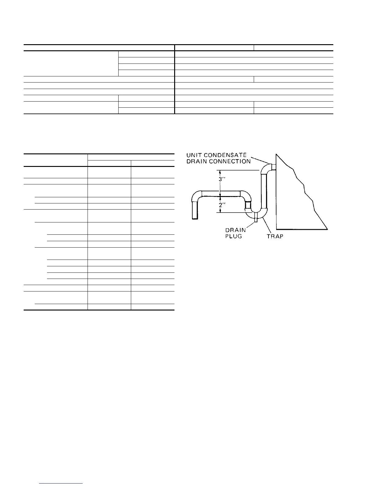
The condensate drain, located on the right end of the unit,
should be connected to an open drain or allowed to discharge
directly onto the ground or roof. A trap MUST be installed. See
Figure 4.
The 3" dimension must equal or exceed the negative static
pressure developed by the supply air blowers. If it doesn’t, the
condensate will not drain properly and will overflow the drain
pan.
The trap must be at least 2" deep to maintain a water seal under
all operating conditions, especially when the blowers are
starting up.
POWER AND CONTROL WIRING
Install electrical wiring in accordance with the latest National
Electrical Code (NFPA Standard No. 70) and for local
regulations. The unit should be grounded in accordance with
these codes.
POWER WIRING
The field power wiring can be brought into the control box
through the 4-1/2" diameter sleeve in the base of the unit
(Figure 5) or through the 3" threaded conduit connector in the
side of the control box (Figure 6). The unit is equipped with a
conduit termination plate above the 4-1/2" diameter sleeve. The
plate has 1-23/32", 2-1/2", and 3-5/8" diameter concentric
knockouts. For units with disconnect switch, the power lugs can
be rotated 90 degrees clockwise to facilitate entrance of the
power wiring from the side of the box. To do this remove the
1/4" bolt holding the power lug. Next remove the slotted spring
pin which keeps the lug from rotating. Turn the power lug 90
degrees clockwise and replace both the slotted spring pin and
the 1/4" bolt.
MODEL DSC 360 480
Voltage Variation, Min/Max
1
200 Volts 187 / 218
230 Volts 216 / 252
460 Volts 432 / 504
575 Volts 540 / 630
Supply Air CFM, Min/Max 9,600 / 14,400 12,800 / 19,200
Wet Bulb Temp. (ÉF) of Air on Evaporator Coil, Min/Max 57 / 72
Dry Bulb Temp. (ÉF) of Air on Condenser Coil, Min/Max
2
0 / 115
Minimum Dry Bulb Temp. (ÉF) of Air On: Gas Fired Heater 20
Maximum Dry Bulb Temp. (ÉF) of Air Off:
Gas Fired Heater 145 155
Electric Heater 180 180
1
Utilization Range “A” in accordance with ARI Standard 110.
2
Low Ambient accessory (Form 530.25-N1.7) may be required for 0ÉF outdoor ambient.
TABLE 1 - APPLICATION DATA
COMPONENT
MODEL
DSC360 DSC480
Outdoor Air Option
Fixed Outdoor Air 75 85
Economizer Option 220 247
Supply Air Motor & Drive
10 HP 145 -
15 HP 185 185
20 HP - 215
Heating Option
Cooling Only 60 65
Natural Gas Heat
G400 200 -
G560 300 300
G800 - 400
Electric Heat
E040 110 110
E060 115 115
E080 120 120
E100 125 125
E120 130 130
Exhaust Fan 160 250
Accessories
Roof Mounting Curb 350 400
End Outlet Kit 105 130
TABLE 2 - COMPONENT WEIGHTS (LBS.)
FIG. 4 - RECOMMENDED DRAIN PIPING
530.25-N3Y
4 Unitary Products Group