Do you have a question about the York DC-120 and is the answer not in the manual?
Alert symbols and signal words (DANGER, WARNING, CAUTION) indicating potential hazards.
Essential safety precautions and warnings before commencing unit installation.
Description of the Simplicity SE control board and its capabilities for cooling applications.
Recommendations for selecting a suitable installation location based on codes and site requirements.
Recommendations for designing and sizing ductwork according to industry standards.
Instructions for field wiring, grounding, and safety compliance with electrical codes.
Recommendations for thermostat location and wiring procedures.
Tables indicating pipe capacity based on length and nominal iron pipe size.
Steps for connecting gas supply, including safety warnings and recommendations.
Overview of available free cooling options: Dry Bulb, Single Enthalpy, Dual Enthalpy.
Step-by-step explanation of free cooling operation based on thermostat and sensor inputs.
Information on adjusting airflow performance data for altitude and temperature variations.
Tables detailing specifications for indoor blowers and power exhaust motors.
Procedures for balancing airflow and measuring air quantity using two methods.
Steps for measuring airflow and using Dry Coil Delta P graphs for calculations.
Instructions for adjusting blower speed using the variable pitch motor sheave.
Detailed explanation of the cooling sequence, including compressor and fan operation.
Description of economizer operation with dual enthalpy sensors, power exhaust, and motorized dampers.
Explanation of cooling system errors, limit switches, and low ambient operation.
Description of the operation sequence for electric heating stages and error handling.
Details on compressor protection mechanisms like Anti-Short Cycle Delay and minimum run times.
Step-by-step description of gas heating ignition, flame stabilization, and operation.
Information on gas heating faults, lock-outs, temperature limits, and flame sensing.
Description of limit switches, pressure switches, and microprocessor failure detection for gas heat.
Pre-start checks, operating instructions, and post-start checks for cooling mode.
Pre-start checks, operating instructions, and post-start checks for gas heating mode.
Procedure for verifying gas heat input rate for the furnace.
Procedure for adjusting manifold gas pressure for heating stages.
Step-by-step guide to adjusting gas valve pressure for first and second stages.
Instructions for charging the unit using Thermal Expansion Devices.
Table listing ignition control flash codes and their corresponding fault conditions.
Covers essential start-up checkpoints common to all package equipment.
Critical safety warnings regarding lethal voltages and moving parts during startup.
Required system information from the specifying engineer for proper equipment startup.
Steps for measuring fan rotation, airflow, and electrical data.
Table for recording nameplate and measured electrical data for unit components.
Data points to record for cooling system operation, including pressures and temperatures.
Procedures for verifying compressor rotation and safety switch operations.
Data points to record for gas heating operation, including manifold pressure and temperature rise.
Checks for proper operation of heating/cooling staging and variable frequency drives.
Final verification of set points, options, panel security, and recording of deficiencies.
| Brand | York |
|---|---|
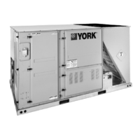
| Model | DC-120 |
| Category | Air Conditioner |
| Language | English |