EasyManua.ls Logo

York DCMF24NWM42Q1 User Manual

York DCMF24NWM42Q1
34 pages
To Next Page IconTo Next Page
Page #1 background imageLoading...
Page #1 background image
LX SERIES
DUCTLESS SINGLE-SPLIT
AIR CONDITIONERS AND HEAT PUMPS
16 SEER – 1 PHASE
3/4 THRU 2 NOMINAL TONS
MODELS: DCMF/DHMF
Due to continuous product improvement, specifications
are subject to change without notice.
Visit us on the web at
www.upgnet.com
Additional rating information can be found at
www.ahridirectory.org
WARRANTY SUMMARY*
Standard 2-Years limited parts warranty.
Standard 6-Years limited compressor warranty.
TECHNICAL
GUIDE
TECHNICAL
GUIDE
FOR DISTRIBUTION USE ONLY - NOT TO BE USED AT POINT OF RETAIL SALE
923178-UTG-B-0114
DESCRIPTION
The Single-Split Series are ductless climate systems. They are
designed with a matching indoor unit for optimum performance and effi-
ciency. These climate systems are supported with accessories and doc-
uments to serve specific functions.
FEATURES
Variable Frequency Rotary Compressor - Twin rotary inverter compressor
on all models features high efficiency operation that modulates down to 15
Hz and as high as 120 Hz for reduced vibration and quiet operation. Brush-
less DC motor uses powerful Neodymium magnets that are approximately
15-20 times stronger than ferrite magnets used in conventional AC compres-
sors. The DC Inverter Control provides continuous operation, while adjusting
capacity according to room temperature. The accurate sensing of cooling or
heating loads prevents frequent changes in capacity and ensures efficient,
economical operation.
Low Ambient Cooling Operation Down to 5 °F - This feature allows for a
space to be air-conditioned even in outdoor temperatures as low as 5 °F.
This cooling ability is important when dealing with server equipment rooms,
surveillance mechanical rooms, restaurant kitchens, fitness centers, and
more.
Load Variation Management System - The outdoor coil thermistor continu-
ously monitors the temperature and communicates with the microprocessor.
Depending on the temperature measured, the compressor will be allowed to
increase the frequency if needed to meet the load or reduce frequency as
the load is reduced.
High Pressure Discharge Temperature - The compressor discharge line
thermistor continuously monitors the temperature and communicates with
the microprocessor. Depending on the temperature measured, the compres-
sor will be allowed to increase the frequency to meet the load or is forced to
run at the current or reduced frequency. If the temperature gets excessively
high, the compressor will be de-energized.
Defrost Control (Heat Pump Models) - Defrost cycle is automatically
enabled if there is a build-up of frost on the outdoor coil. Outdoor fan and
indoor blower operation is terminated during the defrost cycle. H1 is dis-
played on the indoor unit panel on the front cover during a defrost cycle.
Reversing Valve (Heat Pump Models) - 4-way interchange reversing valve
effects a rapid change in direction of refrigerant flow resulting in quick
changeover from cooling to heating and vice versa. Valve operates on sys-
tem pressure differential between outdoor unit and indoor unit.
R-410A Refrigerant - Unit is pre-charged with R410A refrigerant that uses
PVE refrigerant oil. Polyvinyl ether (PVE) is an innovative refrigerant oil spe-
cially formulated for hydrofluorocarbon (HFC) refrigeration systems. In addi-
tion to providing lubricating properties, it also has a number of other applied
advantages that help to increase the reliability of the refrigeration systems
where it is applied.
Refrigerant Line Connections, Service Valve - Outdoor units are designed
with easy service and maintenance in mind. Maintenance points are located
behind easy-access panels, to make installation and service a breeze for a
trained technician. Flare connection lines are located on side of unit cabinet.
Fully serviceable brass service valve prevents corrosion and provide access
to refrigerant system. Shut-off valve that can be fully shut off while 2-way
suction/vapor valve (with service port) may be front seated to manage refrig-
erant charge while servicing system.
Air Deflection Louvers - Horizontal louvers default to the cooling or heating
position when the unit is operating. Horizontal louvers can be set to a preset
oscillating range or fixed position from the wireless remote control. Full oscil-
lating is the default setting when button is pushed. Vertical louvers can be
manually adjusted to direct the airflow for optimal comfort.
Indoor Coil Freeze Protection - The indoor coil thermistor monitors the coil
temperature continuously. Any time the coil temperature drops below 30°F,
the compressor and the outdoor fan (30 seconds later) will be switched off
until the coil temperature rises above 43°F and the compressor has been off
for a minimum of 3 minutes.
I FEEL Function - When I FEEL is activated, the system will satisfy the cool-
ing or heating temperature setpoint where the remote control is located.
When I FEEL is deactivated, the system will satisfy the cooling or heating
temperature setpoint where the indoor unit is located. This feature provides
homeowners with optimum comfort whether they are near or far from the
indoor unit.
Hot Heat Pump (cold air prevention) - In heating mode, the indoor fan will
be delayed from 1 to 3 minutes to allow refrigerant to warm up and avoid
cold blow. This may occur during:
Initial start-up of a heating cycle
Immediately after completion of an Auto mode operation
Heating under extremely low indoor temperatures
Question and Answer IconNeed help?

Do you have a question about the York DCMF24NWM42Q1 and is the answer not in the manual?

York DCMF24NWM42Q1 Specifications

General IconGeneral
BrandYork
ModelDCMF24NWM42Q1
CategoryAir Conditioner
LanguageEnglish

Summary

Description

Features

Variable Frequency Rotary Compressor

Twin rotary inverter compressor with high efficiency and modulation.

Low Ambient Cooling Operation Down to 5 °F

Allows cooling operation in outdoor temperatures as low as 5°F.

Load Variation Management System

Manages compressor frequency based on outdoor coil temperature for load matching.

High Pressure Discharge Temperature

Monitors compressor discharge line temperature to prevent overheating.

Defrost Control (Heat Pump Models)

Automatic defrost cycle for heat pump models to remove frost from outdoor coil.

Reversing Valve (Heat Pump Models)

4-way valve for quick changeover between heating and cooling modes.

R-410A Refrigerant

Uses R410A refrigerant and PVE oil for improved reliability and efficiency.

Refrigerant Line Connections, Service Valve

Design for easy service and maintenance of refrigerant lines and valves.

Air Deflection Louvers

Controls airflow direction with adjustable horizontal and vertical louvers.

Indoor Coil Freeze Protection

Protects indoor coil from freezing by controlling compressor and fan operation.

I FEEL Function

System adjusts to temperature at remote control location for optimal comfort.

Hot Heat Pump (cold air prevention)

Delays indoor fan operation in heating mode to prevent cold air discharge.

Nomenclature

Specifications

AIR CONDITIONERS

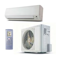
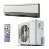
Technical specifications for air conditioner models, including performance and dimensions.

HEAT PUMPS

Product Operation Characteristic Curves

Product Capacity Variation Ratio

Operation Data

COOLING

Operational data for cooling mode, including temperatures, pressures, and frequencies.

HEATING

Operational data for heating mode, including temperatures, pressures, and frequencies.

SOUND DATA

Noise level data for indoor and outdoor units based on fan speed and compressor frequency.

Product Construction View & Dimensions

Indoor Unit Dimensions

Provides dimensions and gross weight for various indoor unit models.

Outdoor Unit Dimensions

Provides dimensions and gross weight for various outdoor unit models.

Refrigerant System Diagram

09K/12K/18K Cooling Only Models

Refrigerant circuit diagram for cooling-only models.

09K/12K/18K Heat Pumps

Refrigerant circuit diagram for heat pump models.

Wiring Diagram

Electrical Wiring

Electrical wiring schematic for 09K and 12K outdoor air conditioner units.

Description of Each Control Operation

Temperature & Current Parameters

Defines key temperature and current parameters used in operation.

Basic Functions

Explains fundamental operational rules for compressor restart and continuous operation.

Cooling Mode

Details operation logic, fan speeds, and temperature settings for cooling mode.

AUTO Mode

Describes the system's automatic mode, including temperature setpoints and mode switching logic.

Dehumidification Mode

Dehumidification Mode Operation

Explains operation parameters and logic for dehumidification mode.

Protection - Dehumidification Mode

Refers to protection measures described in the cooling mode section.

Heating Mode

Heating Mode Operation

Details operational logic, fan speeds, and temperature settings for heating mode.

Defrost Mode Operation

Explains conditions and sequence of operations for defrost mode in heating.

Protection – Heating Mode

Covers cold air prevention and current/frequency protection in heating mode.

Common Protection Functions and Fault Display Under Cool, Heat, Dry and Auto Modes

Overload Protection

Explains overload protection mechanisms for cooling and heating modes based on tube temperature.

High Discharge Temperature Compressor Protection

Details protection against high compressor discharge temperatures.

Communication Fault

Describes system shutdown due to communication signal loss.

Module Protection

Explains module protection mode and restart limitations.

Overload Protection (Voltage/DC Bus)

Covers overload protection related to voltage and DC bus conditions.

Temperature Sensors Faults

Lists faults related to open or short-circuited temperature sensors.

Removal Procedure

Removal Procedure of Indoor Unit

Step-by-step guide for safely disassembling the indoor unit components.

Removal Procedure of Outdoor Unit

Related product manuals