Do you have a question about the York DCPM and is the answer not in the manual?
Details on the twin rotary inverter compressor, its efficiency, and motor technology.
Cooling capacity ratings in BTU/h for various models.
Power consumption in Watts for different models.
Nominal current draw in Amperes for each model.
Seasonal Energy Efficiency Ratio for various models.
Energy Efficiency Ratio for cooling operation.
Operational temperature range for outdoor units in Fahrenheit.
Cooling and Heating capacity ratings in BTU/h.
Power consumption in Watts for heat pump models.
Energy efficiency ratings for cooling and heating.
Efficiency ratings for cooling (EER) and heating (COP).
Operational temperature range for outdoor heat pump units in Fahrenheit.
Nominal cooling capacity in BTU/h for 115V models.
Minimum and maximum cooling capacity in BTU/h.
Seasonal Energy Efficiency Ratio for 115V models.
Energy Efficiency Ratio for 115V models.
Operating temperature range for cooling in Fahrenheit and Celsius.
Operating temperature range for heating in Fahrenheit and Celsius.
Nominal cooling capacity in BTU/h for 115V heat pumps.
Minimum and maximum cooling capacity in BTU/h for heat pumps.
Nominal heating capacity in BTU/h for 115V heat pumps.
Minimum and maximum heating capacity in BTU/h for heat pumps.
Heating Seasonal Performance Factor for 115V heat pumps.
Seasonal Energy Efficiency Ratio for 115V heat pumps.
Energy Efficiency Ratio for 115V heat pumps.
Operating temperature range for cooling in Fahrenheit and Celsius.
Operating temperature range for heating in Fahrenheit and Celsius.
Current vs. Compressor Speed curves for 09K/12K units in cooling mode.
Current vs. Compressor Speed curves for 09K/12K units in heating mode.
Current vs. Compressor Speed curves for 18K/24K units in cooling mode.
Current vs. Compressor Speed curves for 18K/24K units in heating mode.
Current vs. Compressor Speed curves for 30K unit in cooling mode.
Current vs. Compressor Speed curves for 30K unit in heating mode.
Capacity ratio vs. Outdoor Temperature for 09K/12K cooling.
Operational data for cooling mode across different models.
Operational data for heating mode across different models.
Diagram showing refrigerant flow for cooling-only units.
Diagram showing refrigerant flow for heat pump units.
Diagram showing refrigerant flow for 36K cooling-only units.
Diagram showing refrigerant flow for 30K/36K heat pump units.
Electrical wiring schematic for 09K & 12K 115V outdoor AC units.
Electrical wiring schematic for 09K & 12K indoor units.
Electrical wiring schematic for 18K & 24K indoor units.
Electrical wiring schematic for 18K outdoor AC units.
Electrical wiring schematic for 18K indoor units.
Electrical wiring schematic for 24K outdoor AC units.
Electrical wiring schematic for 24K indoor units.
Electrical wiring schematic for 36K outdoor AC units.
Electrical wiring schematic for 36K indoor units.
Electrical wiring schematic for 09K & 12K 115V outdoor heat pumps.
Electrical wiring schematic for 09K & 12K indoor heat pumps.
Electrical wiring schematic for 18K & 24K outdoor heat pumps.
Electrical wiring schematic for 18K & 24K indoor heat pumps.
Electrical wiring schematic for 18K outdoor heat pumps.
Electrical wiring schematic for 18K indoor heat pumps.
Electrical wiring schematic for 24K outdoor heat pumps.
Electrical wiring schematic for 24K indoor heat pumps.
Electrical wiring schematic for 30K outdoor heat pumps.
Electrical wiring schematic for 30K indoor heat pumps.
Electrical wiring schematic for 36K outdoor heat pumps.
General operational rules for compressor restart and minimum run times.
Details on how the unit operates in cooling mode.
Protective functions activated during cooling mode operation.
Details on automatic mode activation and operation.
Details on how the unit operates in dehumidification mode.
Details on how the unit operates in heating mode, including fan delays.
Specifics of heating mode operation, including fan delay.
Procedure and conditions for entering defrost mode.
Protective functions activated during heating mode operation.
Protection against compressor overload in cooling and heating.
Protection against high compressor discharge temperature.
System shutdown due to loss of communication signals.
Protection mechanism for the unit's modules.
Protection against voltage fluctuations and overload.
Faults related to open or short-circuited temperature sensors.
| Cooling Capacity | 9, 000 - 36, 000 BTU |
|---|---|
| SEER | Up to 22 |
| HSPF | Up to 10 |
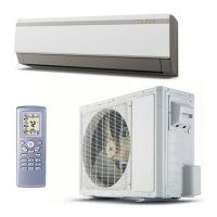
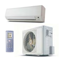
| Type | Mini-Split |
| Refrigerant | R410A |
| Voltage | 208/230V |
| Heating Capacity | 9, 500 - 36, 000 BTU |
| Power Supply | 208/230V, 1 Phase, 60Hz |
| Weight | Varies by model |
| Dimensions (HxWxD) | Varies by model |