EasyManua.ls Logo

York DHMF24CMM42Q1A User Manual

York DHMF24CMM42Q1A
30 pages
To Next Page IconTo Next Page
Page #1 background imageLoading...
Page #1 background image
LX SERIES
DUCTLESS MULTI-ZONE SPLIT
HEAT PUMPS
16 SEER – 1 PHASE
1.5 THRU 3.5 NOMINAL TONS
MODELS:
INDOOR-DHPM/OUTDDOR-DHMF
Due to continuous product improvement, specifications
are subject to change without notice.
Visit us on the web at
www.upgnet.com
Additional rating information can be found at
www.ahridirectory.org
WARRANTY SUMMARY*
Standard 2-Years limited parts warranty.
Standard 6-Years limited compressor warranty.
TECHNICAL
GUIDE
TECHNICAL
GUIDE
FOR DISTRIBUTION USE ONLY - NOT TO BE USED AT POINT OF RETAIL SALE
923212-UTG-A-0113
DESCRIPTION
The Multi Zone Series are ductless climate systems. They are designed
with a matching indoor unit for optimum performance and efficiency.
These climate systems are supported with accessories and documents
to serve specific functions.
FEATURES
Variable Frequency Rotary Compressor - Twin rotary inverter compressor
on all models features high efficiency operation that modulates down to 15
Hz and as high as 120 Hz for reduced vibration and quiet operation. Brush-
less DC motor uses powerful Neodymium magnets that are approximately
15-20 times stronger than ferrite magnets used in conventional AC compres-
sors. The DC Inverter Control provides continuous operation, while adjusting
capacity according to room temperature. The accurate sensing of cooling or
heating loads prevents frequent changes in capacity and ensures efficient,
economical operation.
Low Ambient Cooling Operation Down to 5 °F - This feature allows for a
space to be air-conditioned even in outdoor temperatures as low as 5 °F.
This cooling ability is important when dealing with server equipment rooms,
surveillance mechanical rooms, restaurant kitchens, fitness centers, and
more.
Condenser High Temperature Protection - The outdoor coil thermistor
continuously monitors the temperature and communicates with the micro-
processor. Depending on the temperature measured, the compressor will be
allowed to increase the frequency if needed to meet the load or is forced to
run at the current or reduced frequency. If the temperature gets excessively
high the compressor will be de-energized.
High Pressure Discharge Temperature - The compressor discharge line
thermistor continuously monitors the temperature and communicates with
the microprocessor. Depending on the temperature measured, the compres-
sor will be allowed to increase the frequency to meet the load or is forced to
run at the current or reduced frequency. If the temperature gets excessively
high, the compressor will be de-energized.
Defrost Control (Heat Pump Models) - Defrost cycle is automatically
enabled if there is a build-up of frost on the outdoor coil. Outdoor fan and
indoor blower operation is terminated during the defrost cycle. H1 is dis-
played on the indoor unit panel on the front cover during a defrost cycle.
Reversing Valve (Heat Pump Models) - 4-way interchange reversing valve
effects a rapid change in direction of refrigerant flow resulting in quick
changeover from cooling to heating and vice versa. Valve operates on sys-
tem pressure differential between outdoor unit and indoor unit.
R-410A Refrigerant - Unit is pre-charged with R410A refrigerant that uses
PVE refrigerant oil. Polyvinylether (PVE) is an innovative refrigerant oil spe-
cially formulated for hydrofluorocarbon (HFC) refrigeration systems. In addi-
tion to providing lubricating properties, it also has a number of other applied
advantages that help to increase the reliability of the refrigeration systems
where it is applied.
Refrigerant Line Connections, Service Valve - Outdoor units are
designed with easy service and maintenance in mind. Maintenance points
are located behind easy-access panels, to make installation and service a
breeze for a trained technician. Flare connection lines are located on side of
unit cabinet. Fully serviceable brass service valve prevents corrosion and
provide access to refrigerant system. Shut-off valve that can be fully shut off
while 2-way service valve (with service port) may be front seated to manage
refrigerant charge while servicing system.
Air Deflection Louvers - Horizontal louvers default to the cooling or heating
position when the unit is operating. Horizontal louvers can be set to a preset
oscillating range or fixed position from the wireless remote control. Full oscil-
lating is the default setting when button is pushed. Vertical louvers can be
manually adjusted to direct the airflow for optimal comfort.
Indoor Coil Freeze Protection - The indoor coil thermistor monitors the coil
temperature continuously. Any time the coil temperature drops below 30°F,
the compressor and the outdoor fan (30 seconds later) will be switched off
until the coil temperature rises above 43°F and the compressor has been off
for a minimum of 3 minutes.
I FEEL Function - When I FEEL is activated, the system will satisfy your
cooling or heating temperature setpoint where the remote control is located.
When I FEEL is deactivated, the system will satisfy the cooling or heating
temperature setpoint where the indoor unit is located. This feature provides
homeowners with optimum comfort whether they are near or far from the
indoor unit.
Hot Heat Pump (cold air prevention) - In heating mode, the indoor fan will
be delayed from 1 to 3 minutes to allow refrigerant to warm up and avoid
cold blow. This may occur during:
Initial start-up of a heating cycle
Immediately after completion of an Auto mode operation
Heating under extremely low indoor temperatures
Question and Answer IconNeed help?

Do you have a question about the York DHMF24CMM42Q1A and is the answer not in the manual?

York DHMF24CMM42Q1A Specifications

General IconGeneral
Phase1
RefrigerantR-410A
Cooling Capacity24000 BTU/h
Voltage208-230V
Power Supply208-230V/60Hz/1Ph
Heating Capacity24000 BTU/h

Summary

Technical Guide Overview

Product Description

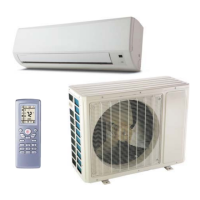
Details the Multi Zone Series ductless climate systems, designed for optimum performance and efficiency.

Key Features

Highlights features like variable frequency rotary compressor, low ambient cooling, and defrost control.

Warranty Summary

Outlines the standard 2-year limited parts and 6-year limited compressor warranty.

Model Nomenclature Explained

Model Number Breakdown

Explains the structure of model numbers including type, SEER, capacity, and configuration.

Performance and Unit Specifications

Performance Ratings

Details cooling and heating capacities, EER, SEER, and HSPF for various models.

Indoor Unit Dimensions and Specs

Provides specifications for indoor units, including fan motor, evaporator, and dimensions.

Outdoor Unit Specifications

Outdoor Unit Performance Data

Lists compressor data, operating ranges, pipe diameters, and air flow for outdoor units.

Outdoor Unit Dimensions and Weight

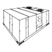
Details dimensions, package dimensions, and weight for outdoor units.

Operation Characteristic Curves

Current vs. Compressor Speed

Graphs showing current draw relative to compressor speed for cooling and heating modes.

Capacity Variation Ratio

Capacity vs. Outdoor Temperature

Charts illustrating capacity ratio changes based on outdoor temperature in cooling and heating.

Operation Data and Sound Levels

Operating Conditions and Frequencies

Table showing temperature conditions, model names, pressures, and compressor frequencies.

Indoor Unit Sound Data

Presents noise levels for indoor units at different fan motor speeds.

Outdoor Unit Noise Levels

Noise vs. Compressor Frequency

Graphs showing outdoor unit noise levels as a function of compressor frequency.

Construction and Dimensions

Indoor Unit Dimensions

Diagrams and table showing dimensions (A, B, C) and gross weight for indoor units.

Outdoor Unit Dimensions

Diagrams and table showing dimensions (A, B, C) and gross weight for outdoor units.

System Diagrams

Refrigerant System Overview

Diagram illustrating the refrigerant flow and components within the multi-zone system.

Electrical Wiring Guide

Details wiring symbols, color codes, and part names for indoor and outdoor units.

Electrical Wiring Details

18K Outdoor Heat Pump Wiring

Diagram and notes for the electrical wiring of the 18K outdoor heat pump unit.

24K Outdoor Heat Pump Wiring

Diagram and notes for the electrical wiring of the 24K outdoor heat pump unit.

Additional Electrical Wiring

30K Outdoor Heat Pump Wiring

Diagram and notes for the electrical wiring of the 30K outdoor heat pump unit.

42K Outdoor Heat Pump Wiring

Diagram and notes for the electrical wiring of the 42K outdoor heat pump unit.

Control Operation and Protections

System Operating Modes

Explains cooling, heating, and dry modes, including fan operation and defrosting.

Mode Conflict and Protection Functions

Details how the system handles conflicting modes and various protection mechanisms.

Sensor Faults and Resistance Tables

Sensor Fault Descriptions

Lists sensors and the conditions that trigger fault detection for each.

Ambient Temperature Sensor Resistance

Table providing resistance values for ambient temperature sensors at various temperatures.

Tube Temperature Sensor Resistance

Tube Sensor Resistance Data

Table showing resistance values for indoor and outdoor tube temperature sensors.

Discharge Temperature Sensor Resistance

Discharge Sensor Resistance Data

Table providing resistance values for outdoor discharge temperature sensors.

Indoor Unit Removal Procedure

Initial Disassembly Steps

Instructions for before disassembly, removing the filter, and removing the display unit.

Indoor Unit Panel and Louver Removal

Panel and Horizontal Louver Removal

Steps for removing the main panel and the horizontal louver assembly.

Electric Box Top Cover Removal

Procedure for removing the top cover of the electric box.

Indoor Unit Case and Cover Removal

Front Case and Earthing Wire Removal

Instructions for removing the front case and the earthing wire.

Main Electric Box Cover Removal

Steps to loosen clasps and remove the main electric box cover.

Indoor Unit Internal Component Removal

Temperature Sensor and Electric Box Removal

Procedure for removing the temperature sensor and the electric box.

Water Tray and Connection Pipe Removal

Steps to remove the water tray and the connection pipe between units.

Indoor Unit Evaporator and Motor Removal

Pipe-Stopping Plate and Damping Board Removal

Instructions for removing the pipe-stopping plate and damping board.

Evaporator and Motor Fixing Plate Removal

Steps for removing the evaporator and the motor fixing plate.

Indoor Unit Fan and Cushion Removal

Cross Flow Blade and Motor Removal

Procedure for removing the cross flow blade and motor assembly.

Cushion Rubber Removal

Instructions for removing cushion rubber from the cross flow blade and base.

Outdoor Unit Removal Procedure

Top Cover and Front Plate Removal

Steps to remove the top panel, valve cover, and front side panel.

Grille and Panel Removal

Instructions for removing the grille and the main outer panel.

Outdoor Unit Guard and Handle Removal

Guard Grille and Handle Removal

Procedure for removing the guard grille and the unit handle.

Right Side Plate and Electric Box Cover Removal

Steps to remove the right side plate and the electric box cover.

Outdoor Unit Electric Box and Fan Removal

Electric Box and Left Side Plate Removal

Instructions for removing the electric box and the left side plate.

Axial Flow Blade Removal

Procedure for removing the axial flow blade from the unit.

Outdoor Unit Motor and Valve Removal

Motor and Motor Support Removal

Steps to remove the motor and its support assembly.

4-Way Valve and Gas/Liquid Valve Removal

Procedure for removing the 4-way valve and the gas/liquid valves.

Outdoor Unit Compressor and Condenser Removal

Compressor and Isolation Sheet Removal

Instructions for removing the compressor and the isolation sheet.

Condenser Support and Chassis Removal

Steps to remove the condenser support plate and the chassis.

Parts and Accessories Catalog

Other Accessories and Mounting Parts

List of part numbers for accessories, mounting hardware, and condensate handling.

Minisplit Linesets and Fittings

Catalog of part numbers for insulated linesets, covers, and various fittings.

Related product manuals