167791-BIM-B-0606
10 Unitary Products Group
LOCATION
Use the following guidelines to select a suitable location for
these units:
1. Unit is designed for outdoor installation only.
2. Condenser coils must have an unlimited supply of air.
Where a choice of location is possible, position the unit
on either north or east side of building.
3. Suitable for mounting on roof curb.
4. For ground level installation, use a level concrete slab
with a minimum thickness of 4 inches. The length and
width should be at least 6 inches greater than the unit
base rails. Do not tie slab to the building foundation.
5. Roof structures must be able to support the weight of the
unit and its options/accessories. Unit must be installed on
a solid, level roof curb or appropriate angle iron frame.
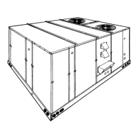
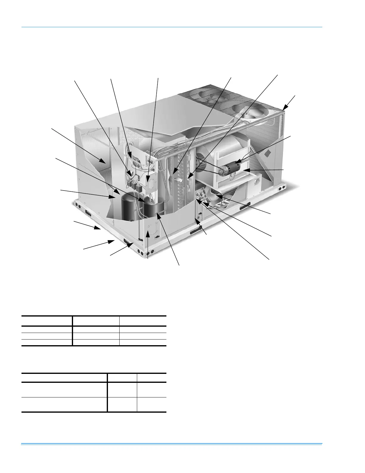
FIGURE 4 - DL/DU COMPONENT LOCATION (DL-10 SHOWN)
Slide-Out Drain
Pan w/ Steel 3/4”
NPT, Female
Connection
Power Ventor Motor
Compressor #1 Access (High-Eff
Compressor w/ crankcase heater)
Belt-Drive
Blower
Motor
Terminal Block
for Hi-Voltage
Connection
Disconnect Location
(Optional Disconnect Switch)
Filter Access
(2” Filters)
Filter-Drier (Solid Core)
Condenser
Section
Two-stage gas heat-
ing to maintain
warm, comfortable
temperature
Intelligent control board for
safe and efficient operation
Side entry power
and control wiring
knockouts
Toolless
door latch
Base Rails w/ Forklift
Slots (3 Sides) & Lift-
ing Holes
Second model
nameplate inside
hinged access
panel
Compressor #2
Access (High-
Eff Compressor
w/ crankcase
heater)
Roof curbs in eight- and
fourteen-inch heights.
Rood curbs for transition-
ing from DHB/DHC/DUS
footprint to the DU/DC
Series footprint are also
available (field-installed
accessory)
Dual stage
cooling for
maximum
comfort
Slide-out motor
and blower
assembly for
ease of adjust-
ment and ser-
vice
Simplicity
®
Control Board
w/Screw Connector for T-
stat Wiring and Network
Connection
TABLE 1: UNIT VOLTAGE LIMITATIONS
Power Rating
1
1.
Utilization range “A” in accordance with ARI Standard 110.
Minimum Maximum
208/230-3-60 187 252
460-3-60 432 504
575-3-60 540 630
TABLE 2: UNIT TEMPERATURE LIMITATIONS
Temperature Min. Max.
Wet Bulb Temperature (°F) of Air on
Evaporator Coil
57 72
Dry Bulb Temperature (°F) of Air on
Condenser Coil
0
1
1.
A low ambient accessory is available for operation
down to -20°F.
125
 Loading...