269326-UIM-A-1106
10 Unitary Products Group
SIDE RETURN/BOTTOM EXTERNAL INSTALLATION
Locate and knock out the square corner locators. These indicate the
size of the cutout to be made in the furnace side panel. Refer to Figure 9.
Install the side filter rack following the instructions provided with that
accessory. If a filter(s) is provided at another location in the return air
system, the ductwork may be directly attached to the furnace side
panel. An accessory filter rack is available for mounting the filter exter-
nal to the cabinet.
Some accessories such as electronic air cleaners and pleated media
may require a larger side opening. Follow the instructions supplied with
that accessory for side opening requirements. Do not
cut the opening
larger than the dimensions shown in Figure 5.
EXTERNAL INSTALLATION FOR
UPFLOW/HORIZONTAL CONFIGURATIONS
1. Select desired filter position for upflow/horizontal (left/right side,
side and bottom). Remove the corresponding cabinet cutouts per
instructions provided.
2. Install the external filter box to the side of the cabinet and secure
to the cabinet as specified in the instructions provided with the air
filter kit. If a side return is to be used, cut out the side of the casing
14" high by 16 1/4" wide using the lances in the casing side as a
guide. DO NOT CUT THE OPENING LARGER THAN 14" X 16 1/
4". It is not permissible to cut out the back of the furnace. For bot-
tom returns you place the external filter box between the return air
plenum and the base of the furnace. The casing bottom is
embossed to indicate where to bend the flanges. Refer to Figure 5
for the maximum return air opening sizes. Seal this connection to
prevent leaks.
Do not cut the opening larger than the dimensions shown in Figure
5.
3. Install the return air duct to the air filter box and secure with
screws. Seal this connection to prevent leaks.
4. Install the field provided filter. Refer to Table 5 for the recom-
mended filter size for your furnace.
NOTE: Air velocity must not exceed 300 feet per minute through low
velocity disposable filters. Air velocity must not exceed 650 feet per
minute through high velocity cleanable permanent filters. Use of a filter
that is too small will cause static pressure in the duct system to be too
high, which will have an adverse effect on heating and cooling opera-
tion.
TABLE 5:
Filter Sizes - Upflow
UPFLOW
Input Air Flow
Cabinet
Size
Side
Return
Bottom/End
Return
MBH kW CFM
m
3
/min
in. cm in. cm
50 14.7 1200 34.0 B 25 x 16 64 x 41 25 x 16 64 x 41
75 22.0 1200 34.0 B 25 x 16 64 x 41 25 x 16 64 x 41
75 22.0 1600 45.3 C 25 x 16 64 x 41 25 x 20 64 x 51
100 29.3 1600 45.3 C 25 x 16 64 x 41 25 x 20 64 x 51
100 29.3 2000 56.6 D (2) 25 x 16 (2) 64 x 41 24 x 24 61 X 61
125 36.6 2000 56.6 D (2) 25 x 16 (2) 64 x 41 24 x 24 61 X 61
150 44.0 2000 56.6 D (2) 25 x 16 (2) 64 x 41 24 x 24 61 X 61
DOWNFLOW
Input Air Flow
Cabinet Size
Top Return (Downflow)
Cleanable Air Filters
Top Return (Downflow)
Disposable Air Filters
MBH kW CFM
m
3
/min
in. cm in. cm
50 14.7 1200 34.0 B 14 x 20 (2) 25 x 51 (2) 10 x 20 (2) 25 x 51
75 22.0 1200 34.0 B 14 x 20 (2) 36 x 51 (2) 14 x 20 (2) 36 x 51
75 22.0 1600 45.3 C 16 x 20 (2) 41 x 51 (2) 16 x 20 (2) 41 x 51
100 29.3 1600 45.3 C 16 x 20 (2) 41 x 51 (2) 16 x 20 (2) 41 x 51
100 29.3 2000 56.6 D 20 x 20 (2) 51 x 51 (2) 20 x 20 (2) 51 x 51
125 36.6 2000 56.6 D 20 x 20 (2) 51 x 51 (2) 20 x 20 (2) 51 x 51
150 44.0 2000 56.6 D N/A N/A N/A N/A
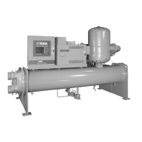
FIGURE 9: Side Return Cutout Markings
CORNER
MARKINGS
FRONT OF
FURNACE
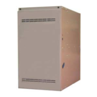
FIGURE 10: Horizontal Mount and Filter
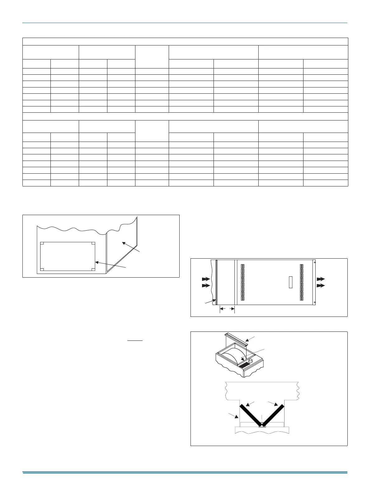
FIGURE 11: Downflow Filter
FURNACE
RETURN
DUCT
18”
MIN.
AIR
FILTER
FILTER RACK
RACK AND FILTERS SECURED
INSIDE BLOWER SECTION
FOR SHIPMENT
DUCTWORK
FILTERS
BRANCH
DUCTS
CROSS SECTION A-A
(with Plenum and filters)
FILTER
RACK
NOTE: FILTER ACCESS THROUGH
DUCTWORK MUST BE PROVIDED
FOR REMOVAL AND CLEANING
 Loading...