269326-UIM-A-1106
Unitary Products Group 17
VENTING INTO AN EXISTING CHIMNEY
For Category I installations, the furnace shall be connected to a factory
built chimney or vent complying with a recognized standard, or a
masonry or concrete chimney lined with a material acceptable to the
authority having jurisdiction. Venting into an unlined masonry chimney
or concrete chimney is prohibited.
Whenever possible, B-1 metal pipe should be used for venting. Where
use of an existing chimney is unavoidable, the following rules must be
followed:
1. The masonry chimney must be built and installed in accordance
with nationally recognized building codes or standards and must
be lined with approved fire clay tile flue liners or other approved
liner material that will resist corrosion, softening, or cracking from
flue gases. THIS FURNACE IS NOT TO BE VENTED INTO AN
UNLINED MASONRY CHIMNEY.
2. This furnace must be vented into a fire clay tile lined masonry
chimney only if a source of dilution air is provided, such as by com-
mon venting with a draft hood equipped water heater. If no source
of dilution air is available, Type B vent must be used, or masonry
chimney vent kit 1CK0603 or 1CK0604 must be used. Refer to the
instructions with the kit to properly apply these masonry chimney
kits.
3. The chimney must extend at least three feet above the highest
point where it passes through a roof of a building and at least two
feet higher than any portion of the building with a horizontal dis-
tance of ten feet.
4. The chimney must extend at least five feet above the highest
equipment draft hood or flue collar.
HORIZONTAL SIDEWALL VENTING
For applications where vertical venting is not possible, the only
approved method of horizontal venting is the use of an auxiliary power
vent. Approved power venters are Fields Controls Model SWG-4Y or
Tjernlund Model GPAK-JT. Follow all application and installation details
provided by the manufacturer of the power vent. Refer to Figures 28
and 29 for typical installation views.
VENT PIPING ASSEMBLY
The final assembly procedure for the vent piping is as follows:
1. Cut piping to the proper length beginning at the furnace.
2. Deburr the piping inside and outside.
3. Dry-fit the vent piping assembly from the furnace to the termination
checking for proper fit support and slope. Piping should be sup-
ported with pipe hangers to prevent sagging. The maximum spac-
ing between hangers is 4 feet (1.22 m).
4. Assemble the vent piping from the furnace to the termination
securing the pipe connections with screws.
VENT CLEARANCES
IMPORTANT: The vent must be installed with the following minimum
clearances as shown in Figure 32, and must comply with local codes
and requirements.
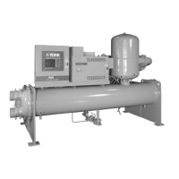
FIGURE 27: Air Inlet, Outlet and Chimney Connections
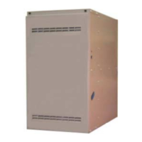
FIGURE 28: Typical Sidewall Vent Application
CHIMNEY OR
GAS VENT
VENTILATION LOUVERS
(Each end of attic)
OUTLET
AIR
FURNACE
WATER
HEATER
INLET AIR DUCT
{Ends 1 ft (30 cm)
above floor}
FAN ASSISTED FURNACE
& WATER HEATER
FAN ASSISTED
FURNACES
VENT
PIPE
HOT
WATER
TANK
FURNACE
OPTIONAL
SIDEWALL
VENT SYSTEM
(field supplied)
EXTERIOR
VENT HOOD
FIGURE 29: Typical Sidewall Vent and Termination Configuration
TABLE 9: Horizontal Sidewall Venting Clearances
Models
Horizontal Vent Length Ft. (m) with 4 Elbows
Pipe Size Min. Vent Length Max. Vent Length
Inches cm Feet meters Feet meters
All Models 4 10.2 4.5 1.37 34.5 10.82
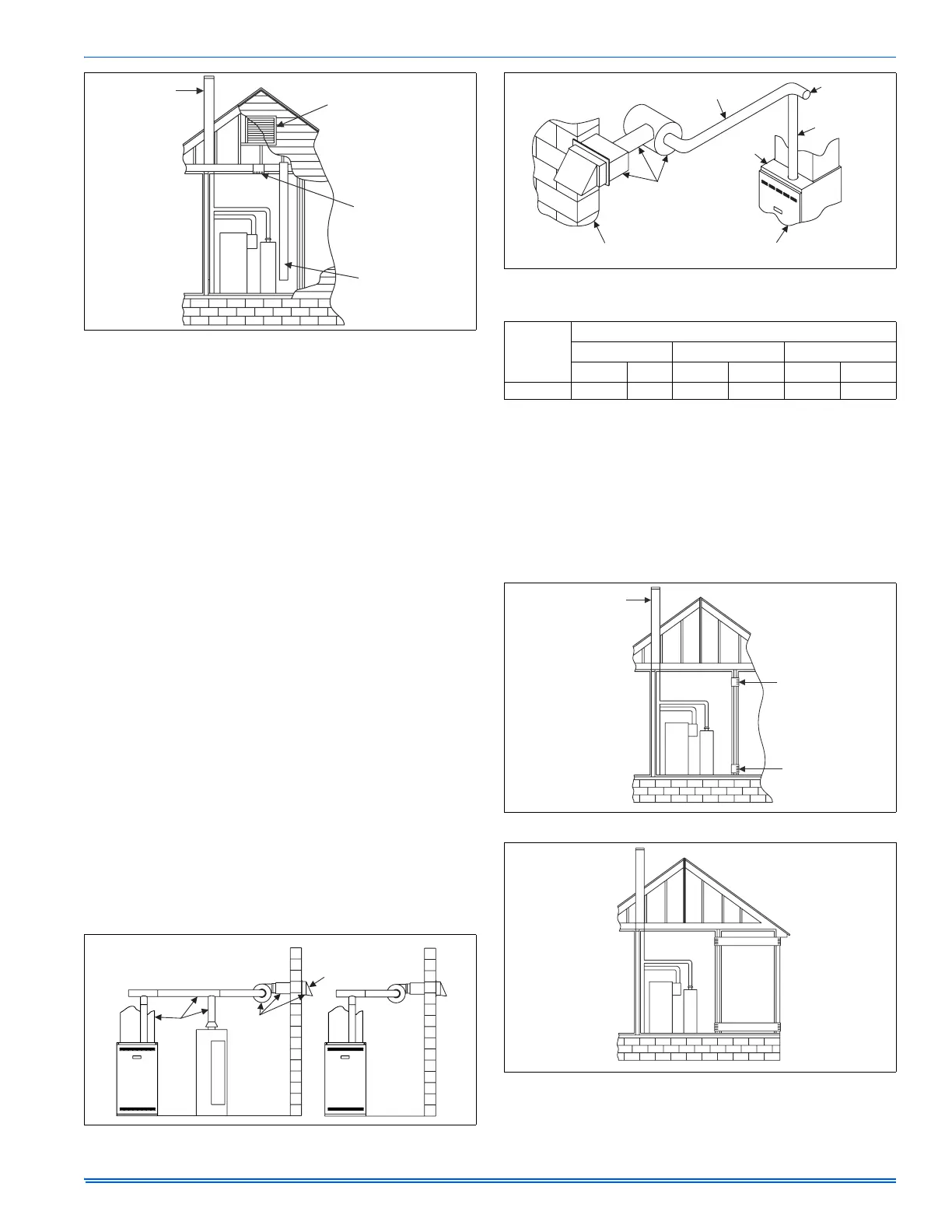
FIGURE 30: Typical Chimney Connections
FIGURE 31: Horizontal Air Inlet, Outlet and Chimney Connections
VENT PIPE
FLUE
PIPE
BURNER
ACCESS
PANEL
CELLAR
WALL
OPTIONAL
SIDEWALL
VENT SYSTEM
(field supplied)
TOP
COVER
VENT
DAMPER
CHIMNEY OR
GAS VENT
OPENING
OPENING
FURNACE
WATER
HEATER
FURNACE
WATER
HEATER
OUTLET
AIR DUCT
INLET
AIR DUCT
 Loading...