269326-UIM-A-1106
Unitary Products Group 13
SECTION V: ELECTRICAL POWER
Electrical Power Connections
Field wiring to the unit must be grounded. Electric wires that are field
installed shall conform to the temperature limitation for 63°F (35°C) rise
wire when installed in accordance with instructions. Refer to Table 7 in
these instructions for specific furnace electrical data.
Nominal external static pressure is 0.50” w.c. at furnace outlet ahead of cooling coils.
Annual Fuel Utilization Efficiency (AFUE) numbers are determined in accordance with DOE Test procedures.
Wire size and over current protection must comply with the National Electrical Code (NFPA-70-latest edition) and all local codes.
SUPPLY VOLTAGE CONNECTIONS
1. Provide a power supply separate from all other circuits. Install
overcurrent protection and disconnect switch per local/national
electrical codes. The switch should be close to the unit for conve-
nience in servicing. With the disconnect or fused switch in the OFF
position, check all wiring against the unit wiring label. Refer to the
wiring diagram in this instruction.
2. Remove the screws retaining the wiring box cover. Route the
power wiring through the opening in the unit into the junction box
with a conduit connector or other proper connection. In the junc-
tion box there will be three wires, a Black Wire, a White Wire and a
Green Wire. Connect the power supply as shown on the unit-wir-
ing label on the inside of the blower compartment door or the wir-
ing schematic in this section. The black furnace lead must be
connected to the L1 (hot) wire from the power supply. The white
furnace lead must be connected to neutral. Connect the green fur-
nace lead (equipment ground) to the power supply ground. An
alternate wiring method is to use a field provided 2” (51 mm) x 4”
(102 mm) box and cover on the outside of the furnace. Route the
furnace leads into the box using a protective bushing where the
wires pass through the furnace panel. After making the wiring con-
nections replace the wiring box cover and screws. Refer to Figure
18.
3. The furnace's control system requires correct polarity of the power
supply and a proper ground connection. Refer to Figure 19.
IMPORTANT: The power connection leads and wiring box may be relo-
cated to the left side of the furnace. Remove the screws and cut wire tie
holding excess wiring. Reposition on the left side of the furnace and fas-
ten using holes provided.
LOW VOLTAGE CONTROL WIRING CONNECTIONS
Install the field-supplied thermostat by following the instructions that
come with the thermostat. With the thermostat set in the OFF position
and the main electrical source disconnected, connect the thermostat
wiring from the wiring connections on the thermostat to the terminal
board on the ignition module, as shown in Figure 19. Electronic thermo-
stats may require the common wire to be connected as shown with the
dashed line in Figure 19. Apply strain relief to thermostat wires passing
through cabinet. If air conditioning equipment is installed, use thermo-
stat wiring to connect the Y and C terminals on the furnace control
board to the yellow and brown wires on the condensing unit (unit out-
side). Refer to Figure 19.
TABLE 6:
High Altitude Conversion
Type
Of Gas
Orifice at
Sea Level
2,000 ft.
(610 m)
3,000 ft.
(914 m)
4,000 ft.
(1219 m)
5,000 ft.
(1524 m)
6,000 ft.
(1829 m)
7,000 ft.
(2134 m)
8,000 ft.
(2438 m)
9,000 ft.
(2743 m)
10,000 ft.
(3048 m)
Natural #42 #42 #43 #43 #43 #44 #44 #45 #46 #47
Propane #54 #54 #55 #55 #55 #55 #55 #56 #56 #56
Use copper conductors only.
TABLE 7: Ratings & Physical / Electrical Data - Upflow Models
Input Output Nominal Airflow Cabinet Width
Total
Unit
AFUE
Air Temp. Rise
MBH kW MBH kW CFM
m
3
min
In. cm Amps °F °C
50 14.7 40 11.7 1200 34.0 17-1/2 44.45 8.0 80.0 30-60 16.7-33.3
75 22.0 60 17.6 1200 34.0 17-1/2 44.45 8.0 80.0 35-65 19.4-36.1
75 22.0 60 17.6 1600 45.3 21 53.34 11.4 80.0 30-60 16.7-33.3
100 29.3 80 23.4 1600 45.3 21 53.34 11.4 80.0 40-70 22.2-38.9
100 29.3 80 23.4 2000 56.6 24 1/2 62.23 11.3 80.0 35-65 19.4-36.1
125 36.6 100 29.3 2000 56.6 24 1/2 62.23 11.3 80.0 40-70 22.2-38.9
150 44.0 120 35.2 2000 56.6 24 1/2 62.23 11.3 80.0 40-70 22.2-38.9
Input
Max. Outlet
Air Temp
Blower
Blower
Size
Max
Over-current
protect
Min.Wire Size
(awg) @ 75 ft.
one way
Operation
Wt.
Operation
Wt.
MBH kW °F °C Hp Amps In. cm LBS Kg
50 14.7 160 71.1 1/2 7.0 10 x 8 25.4 x 20.3 15 14 112 50.8
75 22.0 165 73.9 1/2 7.0 10 x 8 25.4 x 20.3 15 14 118 53.5
75 22.0 160 71.1 1/2 10.4 10 x 10 25.4 x 25.4 15 14 129 58.5
100 29.3 170 76.7 1/2 10.4 10 x 10 25.4 x 25.4 15 14 135 61.2
100 29.3 165 73.9 1 10.3 (2)10 x 6 (2) 25.4 x 15.2 15 14 149 67.6
125 36.6 170 76.7 1 10.3 (2)10 x 6 (2) 25.4 x 15.2 15 14 155 70.3
150 44.0 170 76.7 1 10.3 (2)10 x 6 (2) 25.4 x 15.2 15 14 165 74.8
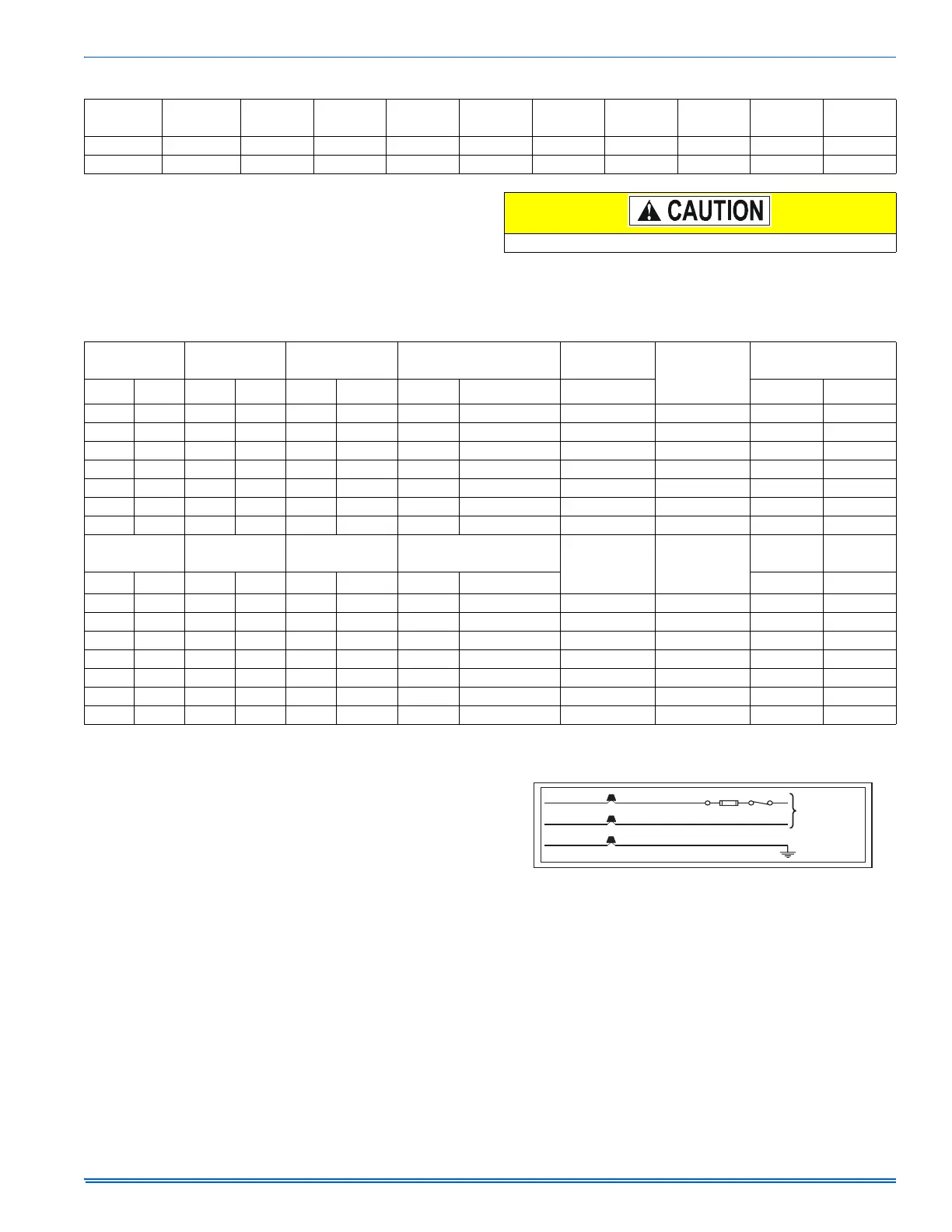
FIGURE 18: Electrical Wiring - Upflow Position
BLK
WHT
GRN
BLK (HOT)
WHT (NEUTRAL)
GRN
NOMINAL
120 VOLT
 Loading...