269326-UIM-A-1106
Unitary Products Group 27
APPLYING FILTER PRESSURE DROP TO
DETERMINE SYSTEM AIRFLOW
To determine the approximate airflow of the unit with a filter in place, fol-
low the steps below:
1. Select the filter type.
2. Select the number of return air openings or calculate the return
opening size in square inches to determine the proper filter pres-
sure drop.
3. Determine the External System Static Pressure (ESP) without the
filter.
4. Select a filter pressure drop from the table based upon the number
of return air openings or return air opening size and add to the
ESP from Step 3 to determine the total system static.
5. If total system static matches a ESP value in the airflow table (i.e.
0.20 w.c. (50 Pa), 0.60 w.c. (150 Pa), etc.,) the system airflow cor-
responds to the intersection of the ESP column and Model/Blower
Speed row.
6. If the total system static falls between ESP values in the table (i.e.
0.58 w.c. (144 Pa), 0.75 w.c. (187 Pa), etc.), the static pressure
may be rounded to the nearest value in the table determining the
airflow using Step 5 or calculate the airflow by using the following
example.
Example: For a 75,000 BTUH (21.98 kW) furnace with 2 return open-
ings and operating on high-speed blower, it is found that total system
static is 0.38” w.c. To determine the system airflow, complete the follow-
ing steps:
Obtain the airflow values at 0.30 w.c. (75 Pa) & 0.40 w.c. (99.6 Pa) ESP.
Airflow @ 0.30”: 1408 CFM (39.8 m
3
/min)
Airflow @ 0.40”: 1343 CFM (38.0 m
3
/min)
Subtract the airflow @ 0.30 w.c. (75 Pa) from the airflow @ 0.40 w.c.
(199.6 Pa) to obtain airflow difference.
1343 - 1408 = -65 CFM (1.89 m
3
/min)
Subtract the total system static from 0.30 w.c. (75 Pa) and divide this
difference by the difference in ESP values in the table, 0.40 w.c.
(99.6 Pa) - 0.30 w.c. (75 Pa), to obtain a percentage.
(0.38 - 0.30) / (0.40 - 0.30) = 0.8
Multiply percentage by airflow difference to obtain airflow reduction.
(0.8) X (-65) = -52
Subtract airflow reduction value to airflow @ 0.30 w.c. (75 Pa) to obtain
actual airflow @ 0.38 inwc (94.6 Pa) ESP.
1408 - 52 = 1356
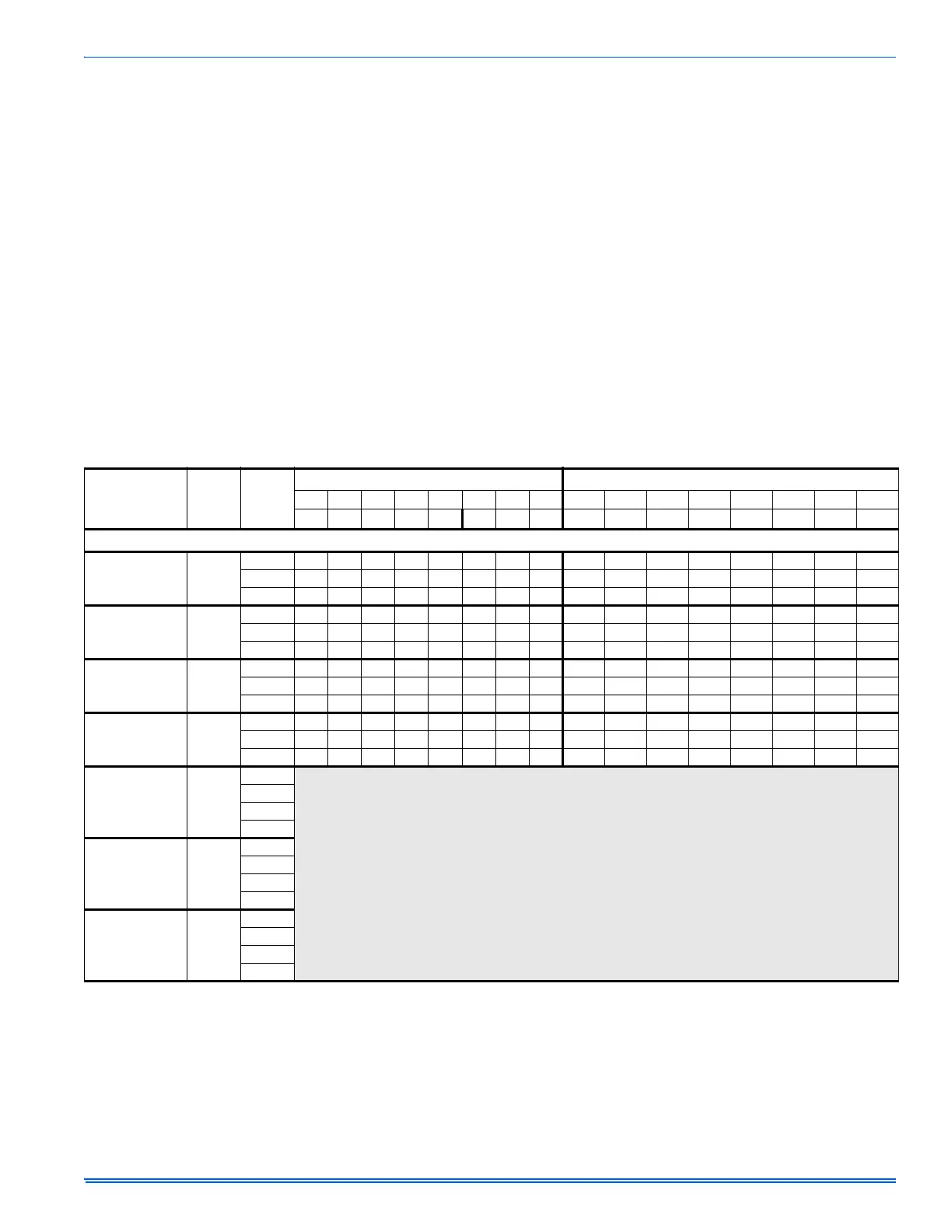
TABLE 17:
Blower Performance - CFM
BTU/H (kW)
Input
Cabinet
Size
Speed
Tap
External Static Pressure, Inches WC External Static Pressure (kPa)
0.1 0.2 0.3 0.4 0.5 0.6 0.7 0.8 (0.025) (0.050) (0.075) (0.099) (0.124) (0.149) (0.174) (0.199)
CFM CFM CFM CFM CFM CFM CFM CFM
m
3
/min m
3
/min m
3
/min m
3
/min m
3
/min m
3
/min m
3
/min m
3
/min
UPFLOW, SINGLE SIDE RETURN (WITHOUT FILTER)
50 (14.7)
1
B
High 1411 1360 1289 1218 1154 1075 983 882 40.0 38.5 36.5 34.5 32.7 30.4 27.8 25.0
Med 1213 1177 1134 1085 1022 960 880 782 34.3 33.3 32.1 30.7 28.9 27.2 24.9 22.1
Low 887 884 871 848 814 775 726 656 25.1 25.0 24.7 24.0 23.0 21.9 20.6 18.6
75 (22.0
1
B
High 1535 1470 1408 1343 1275 1202 1115 1014 43.5 41.6 39.9 38.0 36.1 34.0 31.6 28.7
Med 1215 1199 1182 1151 1106 1039 976 887 34.4 34.0 33.5 32.6 31.3 29.4 27.6 25.1
Low 875 874 864 847 827 799 736 658 24.8 24.7 24.5 24.0 23.4 22.6 20.8 18.6
75 (22.0)
1
C
High 1792 1724 1630 1552 1462 1367 1264 1152 50.7 48.8 46.2 43.9 41.4 38.7 35.8 32.6
Med 1597 1555 1496 1444 1372 1287 1190 1086 45.2 44.0 42.4 40.9 38.9 36.4 33.7 30.8
Low 1115 1140 1167 1183 1149 1093 1023 939 31.6 32.3 33.0 33.5 32.5 31.0 29.0 26.6
100 (29.3)
1
C
High 1868 1781 1690 1600 1498 1396 1277 1156 52.9 50.4 47.9 45.3 42.4 39.5 36.2 32.7
Med 1602 1553 1503 1447 1376 1287 1181 1060 45.4 44.0 42.6 41.0 39.0 36.4 33.4 30.0
Low 1147 1147 1147 1147 1132 1078 1009 918 32.5 32.5 32.5 32.5 32.1 30.5 28.6 26.0
100 (29.3)
2
D
High
NOT ALLOWED
Med-High
Med-Low
Low
125 (36.6)
3
D
High
Med-High
Med-Low
Low
150(44.0)
2
D
High
Med-High
Med-Low
Low
 Loading...