EasyManua.ls Logo

York H5CE150A50 User Manual

York H5CE150A50
16 pages
To Next Page IconTo Next Page
Page #1 background imageLoading...
Page #1 background image
CONTENTS
GENERAL. . . . . . . . . . . . . . . . . . . . . . . . . . . . . . . . . . . . 3
REFERENCE . . . . . . . . . . . . . . . . . . . . . . . . . . . . . . . . . 3
RENEWAL PARTS. . . . . . . . . . . . . . . . . . . . . . . . . . . . . 3
INSPECTION . . . . . . . . . . . . . . . . . . . . . . . . . . . . . . . . . 3
INSTALLATION . . . . . . . . . . . . . . . . . . . . . . . . . . . . . . . 3
START-UP . . . . . . . . . . . . . . . . . . . . . . . . . . . . . . . . . . 11
OPERATION. . . . . . . . . . . . . . . . . . . . . . . . . . . . . . . . . 12
MAINTENANCE . . . . . . . . . . . . . . . . . . . . . . . . . . . . . . 15
See the following page for a complete Table of Contents.
NOTES, CAUTIONS AND WARNINGS
Installer should pay particular attention to the words:
NOTE, CAUTION, and WARNING. Notes are intended to
clarify or make the installation easier. Cautions
are given
to prevent equipment damage. Warnings are given to
alert installer that personal injury and/or equipment dam-
age may result if installation procedure is not handled
properly.
INSTALLATION
MANUAL
CAUTION: READ ALL SAFETY GUIDES BEFORE YOU
BEGIN TO INSTALL YOUR UNIT.
SAVE THIS MANUAL
SPLIT-SYSTEM
CONDENSING UNIT
(AIR COOLED)
MODELS: H5CE150, 180 & 240
(WORLD 50 HZ)
292424-XIM-A-0307
Question and Answer IconNeed help?

Do you have a question about the York H5CE150A50 and is the answer not in the manual?

York H5CE150A50 Specifications

General IconGeneral
BrandYork
ModelH5CE150A50
CategoryAir Conditioner
LanguageEnglish

Summary

GENERAL

REFERENCE

NOMENCLATURE

RENEWAL PARTS

INSPECTION

INSTALLATION

LIMITATIONS

LOCATION

ROOF-TOP LOCATIONS

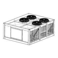
Guidelines for selecting roof locations, emphasizing structural strength and support.

GROUND LEVEL LOCATIONS

Requirements for concrete slabs or piers for ground-level unit installation.

RIGGING AND HANDLING

CLEARANCES

POWER AND CONTROL WIRING

POWER WIRING

Checking power supply voltage, wire size, disconnect switch, and fuses.

CONTROL WIRING

Routing low voltage control wires from the unit to the thermostat and blower controller.

SERVICE VALVES

COMPRESSOR CRANKCASE HEATER

REFRIGERANT PIPING

GENERAL GUIDELINES

Best practices for installing refrigerant piping, including tubing type and brazing.

START-UP

CRANKCASE HEATER

Ensuring the crankcase heater is energized for at least 8 hours before compressor start.

PRE-START CHECK

A checklist of essential items to verify before powering up and operating the unit.

INITIAL START-UP

OPERATION

OPERATIONAL MODES

Details on blower operation (continuous/intermittent) and pump out option features.

SEQUENCE & CONTROLS

Overview of operation sequence, safety controls, and system monitoring.

COOLING SEQUENCE OF OPERATION

FLASH CODES

UNIT CONTROL BOARD

UNIT CONTROL BOARD FLASH CODES

Table detailing flash codes, their descriptions, and corresponding LED indicators.

CONDENSER FAN OPERATION

SAFETY FEATURES

SECURE OWNER'S APPROVAL

MAINTENANCE

SERVICE & REPLACEMENT

Procedures for cleaning condenser surfaces, lubrication, and compressor replacement.

Related product manuals