Do you have a question about the York IDH072B21S Series and is the answer not in the manual?
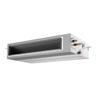
Inspect the unit for transit damage and verify model details upon receiving the product.
Follow all warnings and cautions to reduce the risk of injury or death during installation and operation.
Follow specific precautions for unit mounting, location, and avoiding hazardous environments.
Adhere to strict safety measures for handling refrigerants to prevent injury or equipment damage.
Take precautions to prevent electric shock, fire, or explosion during electrical work.
Proper handling of the unit and ensuring correct condensate drainage to prevent damage.
Combine indoor/outdoor units and handle the unit carefully during transportation.
Check the list of included accessories such as washers, clamps, and insulation.
List of necessary tools and measuring instruments for installation, including specific refrigerant tools.
Select a suitable location with proper clearance, avoiding obstacles and hazardous conditions.
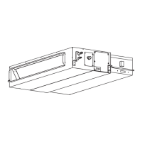
Determine location, mount suspension bolts, and hang the indoor unit securely.
Mark positions for bolts and pipe connections, and understand installation dimensions.
Ensure the unit is horizontal and slightly sloped for proper drainage.
Connect the supply duct to the indoor unit using canvas ducts to prevent abnormal sound vibration.
Install, select capacity, and connect the auxiliary heater following local codes and safety guidelines.
Select correct piping sizes and prepare clean copper pipes, ensuring no dust or moisture.
Connect refrigerant pipes, discharge gas, and braze carefully, protecting thermistors from heat.
Insulate pipes after checking for leaks and perform evacuation and refrigerant charging.
Install condensate piping with a downward slope, ensuring proper drainage and avoiding corrosive gases.
Check that water flows smoothly and no leakage occurs after completing condensate piping and wiring.
Ensure correct wiring capacity, grounding, and use of GFCI for safe electrical connections.
Install appropriate wire sizes, breakers, fuses, and GFCI according to codes.
Connect power supply, communication cables, and wired controller cables according to diagrams.
Configure DIP switches for unit numbering, capacity code, and refrigerant cycle settings.
Select and set various functions such as test run, thermistor, and setback using the wired controller.
Verify electrical resistance, wiring connections, and DIP switch settings before performing test run.
Conduct the test run procedure to confirm proper operation of the unit and system.
Identify and resolve issues using the provided alarm code table for troubleshooting.
| Brand | York |
|---|---|
| Model | IDH072B21S Series |
| Category | Air Conditioner |
| Language | English |