550.13-TG2Y (1001)
Unitary Products Group 3
DESCRIPTION
Evaporator blower units are desi
ned with two distinct mod-
ules to provide maximum application flexibilit
. The 30 and 40
ton units are shipped as sin
le packa
es with the blower
module mounted on top of the coil module, The blower mod-
ule can be repositioned in the field to meet almost an
instal-
lation requirement. Blower and coil modules for the 50 ton
units are shipped separatel
to simplif
handlin
. These mod-
ules can be connected in the field with the same flexibilit
as
the smaller units.
The blower module includes the blower wheels and room for
a field-mounted motor and drive. The coil module includes
direct expansion coils, 1 in. throwawa
filters, liquid line sole-
noid valves for both capacit
reduction and pumpdown, ther-
mal expansion valves, distributors and a condensate drain
pan.
Ever
evaporator coil is pressurized with air to 325 psi
and
leak tested under water. After the headers are brazed onto
the coil and the coil is installed in the unit, the coil is pressur-
ized with a combination of refri
erant-22 and nitro
en to 150
psi
for pressure testin
and additional leak testin
. After the
coil is evacuated and deh
drated, it is pressurized with a
holdin
char
e of refri
erant-22 for stora
e and/or shippin
.
Steam coils, hot water coils, base sections, suspension hard-
ware, blower motors and drive packa
es are available as
field-installed accessories to provide additional application
flexibilit
.
These evaporator blowers, combined with condensin
units,
provide
ears of quiet, efficient and dependable operation.
These units are manufactured under ISO 9001 Qualit
S
s-
tem Certification.
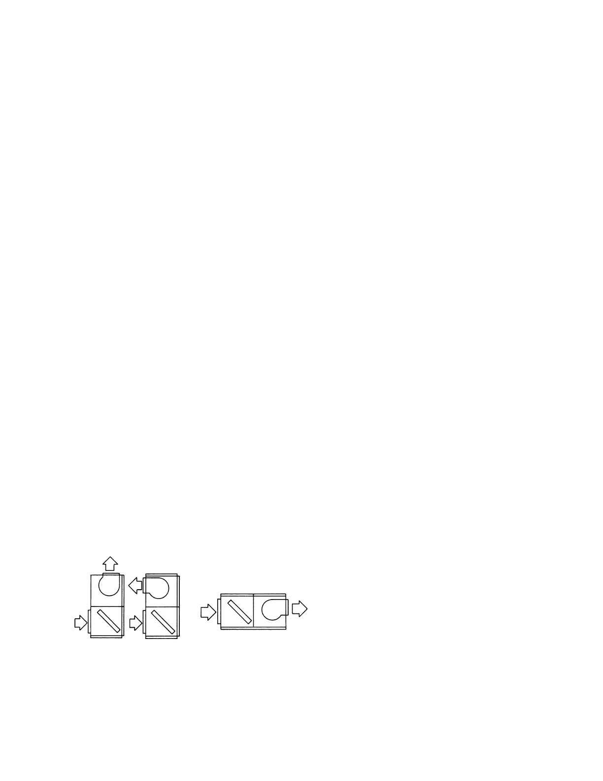
MODULAR DESIGN
These evaporator blowers can be arran
ed for a variet
of air
dischar
e patterns in either the horizontal or the vertical posi-
tion.
The above illustration shows three of the common installation
arran
ements. Refer to the unit installation instructions for
other possibilities.
Units ma
be bottom-supported or ceilin
-suspended and
can be arran
ed to meet almost an
space or duct require-
ments. Each unit is available with a choice of blower motors,
drive packa
es and other accessories to make them suitable
for most applications.
FACTORY-MOUNTED COMPONENTS
PART LOAD OPERATION These evaporator blowers have
multiple coils with pre-piped distributors, expansion valves
and solenoid valves. Field modifications are not required for
part load operations. Capacit
reduction not onl
provides
economical operation, but also maintains more even temper-
ature and humidit
levels in the conditioned space.
EASY SERVICE Serviceable expansion valves are provided
on ever
unit. These superior valves are factor
-installed to
provide man
ears of trouble-free operation. If service is
required, it is not necessar
to unbraze an
joints.
PUMPDOWN Evaporator blowers include a solenoid valve
for non-rec
clin
pumpdown. When the coolin
requirement
in the conditioned space is satisfied, the refri
erant is
pumped into the hi
h side of the s
stem.
ACCESSORIES
BASE SECTIONS (30 and 40 ton onl
) Base sections can
used to elevate units above the floor. If desired, outdoor air
ma
be introduced throu
h these sections b
cuttin
an
access openin
to accommodate the outdoor air duct con-
nection. These bases have a durable finish to match the
evaporator blower unit. The
ma
have to be insulated for
certain applications.
SUSPENSION PACKAGES These accessories can be used
to suspend horizontal units from above without interferin
with access to the unit. The
can also be used for elevatin
a
floor-mounted unit (either horizontal or vertical) to provide
additional hei
ht for the installation of a trap at the conden-
sate drain connection. All suspension packa
es can be used
with vibration isolators.
HOT WATER COILS Drainable water coils are available for
field installation between the blower and the coil modules of
both horizontal and vertical units. Since their casin
s match
the dimensions and the finish of the basic units, the
become
an inte
ral part of the unit after installation. The coils slide out
of their casin
s for eas
installation. Coils have copper tubes
that have been mechanicall
expanded into aluminum fins.
Both headers are located on the same end of the coil. Coils
are leak-tested at 325 psi
under water and dried before their
connections are capped for stora
e and shippin
.
STEAM COILS (LEU360 onl
) A steam coil is available on
the LEU360 for installation between the blower and coil mod-
FIGURE 1 : UNIT INSTALLATION
 Loading...