EasyManua.ls Logo

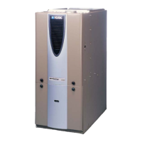
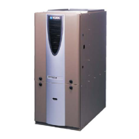
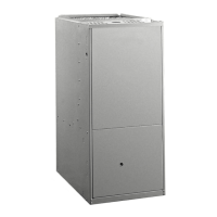
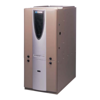
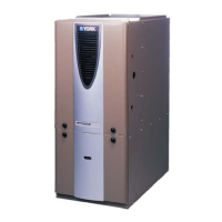
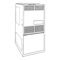
York P*DH User Manual

York P*DH
40 pages
To Next Page IconTo Next Page
Page #1 background imageLoading...
Page #1 background image
CONTENTS
GENERAL INFORMATION . . . . . . . . . . . . . . . . . . . . . . . 2
SPECIFIC UNIT INFORMATION . . . . . . . . . . . . . . . . . . 3
DUCTWORK . . . . . . . . . . . . . . . . . . . . . . . . . . . . . . . . . . 7
GAS PIPING . . . . . . . . . . . . . . . . . . . . . . . . . . . . . . . . . 11
ELECTRICAL POWER CONNECTION . . . . . . . . . . . . 12
ELECTRICAL CONTROL CONNECTIONS . . . . . . . . . 13
COMBUSTION AIR AND VENT SYSTEM . . . . . . . . . . 14
CONDENSATE PIPING . . . . . . . . . . . . . . . . . . . . . . . . 24
SAFETY CONTROLS . . . . . . . . . . . . . . . . . . . . . . . . . . 25
START-UP AND ADJUSTMENTS . . . . . . . . . . . . . . . . 26
FURNACE ACCESSORIES . . . . . . . . . . . . . . . . . . . . . 31
OPERATION AND MAINTENANCE . . . . . . . . . . . . . . . 33
TROUBLESHOOTING . . . . . . . . . . . . . . . . . . . . . . . . . 36
INSTALLATION
INSTRUCTION
CAUTION: READ ALL SAFETY GUIDES BEFORE YOU
START TO INSTALL YOUR FURNACE.
SAVE THIS MANUAL
HIGH EFFICIENCY
GAS-FIRED FURNACES
TUBULAR HEAT EXCHANGER SERIES
MODELS: P*UR / G9T-UP / FG9-UP (Upflow)
40 - 140 MBH INPUT
MODELS: P*DH / G9T-DH / FG9-DH (Downflow / Horizontal)
40 - 120 MBH INPUT
035-17477-001 Rev. A (801)
EFFICIENCY
RATING
CERTIFIED

Other manuals for York P*DH

Questions and Answers:

York P*DH Specifications

General IconGeneral
BrandYork
ModelP*DH
CategoryFurnace
LanguageEnglish

Summary

General Information

Description

Provides an overview of the furnace's design, intended applications, and general operational parameters.

Notes, Cautions & Warnings

Explains the different types of advisory messages used throughout the manual to ensure safety and proper installation.

Specific Unit Information

Limitations & Location

Outlines installation restrictions, model approvals, and preferred locations for the furnace.

Clearances for Access

Recommends minimum clearances around the unit for proper servicing and maintenance access.

Below Freezing Locations

Provides guidance for installations in areas that may experience temperatures below freezing.

Ductwork

Upflow Models

Instructions for connecting the supply plenum and return duct for upflow configurations.

Downflow/Horizontal Models

Details for cooling coil transition, filters, and plenum for downflow/horizontal setups.

Gas Piping

Inlet Gas Pressure Range

Specifies the required gas pressure for natural gas and propane operation.

Adjustment of Manifold Gas Pressure

Describes how to measure and adjust the gas pressure to the burners.

Electrical Connections

Electrical Power Connection

Details the procedures for making the main electrical power connection to the unit.

Electrical Control Connections

Explains wiring for the thermostat, accessories, and internal control circuits.

Accessory Connections

Details on connecting electronic air cleaners, humidifiers, and other accessories.

Combustion Air and Vent System

Method One: Two Pipe Sealed System

Guidelines for a two-pipe system using outdoor air for combustion and venting.

Method Two: One Pipe System

Instructions for a single-pipe system using ambient air for combustion.

Method Three: Two Pipe System Using Ventilated Attic Space

Procedures for a two-pipe system drawing combustion air from a ventilated attic.

Vent Termination (2-Pipe)

Specifies requirements for terminating 2-pipe venting systems.

Vent Terminal Location Clearances

Details minimum clearances for vent terminal installations.

Safety Controls

Pressure Switches

Explains the function of pressure switches monitoring airflow and venting.

Limit Controls

Describes the high-temperature limit control for over-temperature protection.

Start-Up and Adjustments

Ignition System Sequence

Details the step-by-step process for furnace ignition and blower operation.

Checking Gas Input

Guides on measuring and verifying the gas input rate for natural gas.

Operation and Maintenance

Sequence of Operation

Describes the furnace's operational sequence for heating and cooling modes.

Blower Care

Instructions for cleaning and maintaining the blower motor and wheel.

Troubleshooting

Furnace Control Diagnostics

Explains how to interpret fault codes indicated by the control module's LED.

Ignition Control Fault Codes

Lists and describes various fault codes related to the ignition control system.

Wiring Diagrams

Upflow Models

Provides the electrical wiring diagram for upflow furnace models.

Downflow/Horizontal Models

Provides the electrical wiring diagram for downflow/horizontal furnace models.

Related product manuals