035-17480-000 Rev. A (800)
6 Unitary Products Group
ALL DIMENSIONS ARE IN INCHES, AND ARE APPROXIMATE.
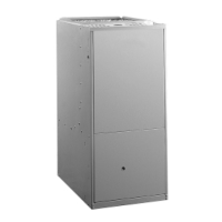
FIGURE 1 : Dimensions - Upflow Models (P*XU/G9D-UH)
TABLE 1: RATINGS & PHYSICAL / ELECTRICAL DATA - UPFLOW MODELS
MODELS P*XU/G9D—UP
AFUE
*
LOW FIRE
TEMP RISE
°F
HIGH FIRE
TEMP RISE
°F
MAX
.
OUTLET
AIR TEMP
.
°
F
BLOWER
TOTAL
UNIT
AMPS
MAX OVER
-
CURRENT
PROTECT
†
MIN WIRE
SIZE
(AWG)@
75
FT.
ONE WAY
†
INPUT
MBH
H
/L
OUTPUT
MBH H
/L
NOM
. CFM HP
BLOWER
AMPS
SIZE
60/39 55/36 1200 94.0 25 - 55 35 - 65 175 1/2 7.0 11 12.0 20 14
80/52 74/48 1200 93.5 20 - 50 35 - 65 165 1/2 7.0 11 12.0 20 14
80/52 76/48 1600 93.5 20 - 50 30 - 60 160 3/4 11.5 11 12.0 20 14
100/65 93/60 1400 93.5 25 - 55 45 - 75 175 1/2 10.7 10 12.0 20 14
100/65 94/60 2000 94.0 20 - 50 30 - 60 160 1 12.2 11 14.0 20 12
120/78 112/72 2000 94.0 20 - 50 45 - 75 175 1 12.2 11 14.0 20 12
*.
AFUE numbers are determined in accordance with DOE test procedures
†.
Wire size and overcurrent protection must comply with the National Electrical Code (NFPA-70-latest edition).
• For altitudes above 2,000 ft., reduce capacity 4% for each 1,000 ft. above sea level. Refer to Form 650.78-N1.1V.
• Wire size based on copper conductors, 60°C, 3% voltage drop.
• Continuous return air temperature must not be below 55°F.
Models P*XU &
G9D—UP
ABCDE
60 / 55 / 1200 / “B” 17-1/2 16-1/4 13-1/8 2 2
80 / 75 / 1200 / “B” 17-1/2 16-1/4 13-1/8 2 2
80 / 75 / 1600 / “C” 21 19-3/4 16-5/8 2 2
100 / 95 / 1400 / “C” 21 19-3/4 16-5/8 2 2
100 / 95 /2000 / “C” 21 19-3/4 16-5/8 2 2
120 / 112 / 2000 / “D” 24-1/2 23-1/4 20-1/8 3
2(3)
*
*.
Vent pipe must be increased to 3” on this unit.
TO P IM AG E
Vent C onnection
-
(v e n t s iz e )
B
FRO N T
In ta k e
onnection
,
20
BO TTO M IM AG E
(F R O N T )
23
C
3/4"
FLANG E
A
28-1/2
(W IT H K .O .
REM OVED)
20
Gas Pipe Entry
1 1/4 x 2 1/2
(All gas pipe connections
are 1/2" NPT)
B
2-3/4
6-1/8
A
Front
9 -7/8
6 -7/8
28 -1/2
Optional Side Return
Cut-Out (Either Side)
Condensate Drain
7/8 Junction
Box Hole
Left Side
6 3/8
1 1/4
T-Stat
Wiring
7/8" K.G.
Right Side
6
22-3/4
3/4
1-3/4
8-7/8
14 -1/2
3-1/8
1-3/4
4-1/8
45
20-5/8
3/4

 Loading...