246813-YTG-D-0108
Unitary Products Group 3
Annual Fuel Utilization Efficiency (AFUE) numbers are determined in accordance with DOE Test procedures.
Wire size and over current protection must comply with the National Electrical Code (NFPA-70-latest edition) and all local codes.
The furnace shall be installed so that the electrical components are protected from water.
NOTES:
1. Wire size based on copper conductors, 60°C, 3% voltage drop.
2. Continuous return air temperature must not be below 55°F.
3. Air flows above 1800 CFM require either return from two sides or one side plus bottom.
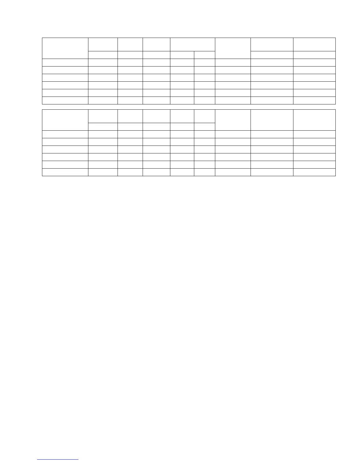
ELECTRICAL AND PERFORMANCE DATA
Models
Input
Max/Min
Output
Max/Min
Blower
Size
Blower7
Max.
Over-current
Protect
Air Temp. Rise
Maximum Input
Air Temp. Rise
Minimum Input
MBH MBH In. HP Amps °F °F
PC9B12N060UP11 60/21 57/20 11 x 8 1/2 7.7 20 40 - 70 20 - 50
PC9B12N080UP11 80/28 76/26 11 x 8 1/2 7.7 20 40 - 70 20 - 50
PC9C16N080UP11 80/28 76/26 11 x 10 3/4 9.6 20 40 - 70 20 - 50
PC9C16N100UP11 100/35 95/33 11 x 10 3/4 9.6 20 40 - 70 20 - 50
PC9C20N100UP11 100/35 95/33 11 x 11 1 12.8 20 40 - 70 20 - 50
PC9D20N120UP11 120/42 115/39 11 x 11 1 12.8 20 40 - 70 20 - 50
Models
Max. Outlet
Air Temp.
Nominal
Airflow
Cabinet
Width
Total
Unit
AFUE
Min. Wire Size
(awg) @ 75 ft.
One Way
Approximate
Operating Weight
Power Supply
(Voltage-PH-Hz)
°F CFM In. Amps %
PC9B12N060UP11 170 1200 17-1/2 9 95.0 14 135 115-1-60
PC9B12N080UP11 170 1200 17-1/2 9 95.0 14 142 115-1-60
PC9C16N080UP11 170 1600 21 12 95.0 14 157 115-1-60
PC9C16N100UP11 170 1600 21 12 95.0 14 162 115-1-60
PC9C20N100UP11 170 2000 21 14 95.0 12 164 115-1-60
PC9D20N120UP11 170 2000 24-1/2 14 95.0 12 180 115-1-60
 Loading...