EasyManua.ls Logo

York RecipPak YEAJ66HT9 User Manual

York RecipPak YEAJ66HT9
92 pages
To Next Page IconTo Next Page
Page #1 background imageLoading...
Page #1 background image
INSTALL., OPER., MAINT.
RecipPak LIQUID CHILLERS
AIR COOLED – RECIPROCATING HERMETIC
Supersedes: See Back Page
Form 150.60-NM4 (1095)
60 HZ MODELS
YEAZ88DR6, YEAJ44DR6, YEAJ44HT6, YEAJ54ES6,
YEAJ55HT8, YEAJ65HT8, YEAJ66MT8
50 HZ MODELS
YEAJ44DR7, YEAJ55DR7, YEAJ55HT7, YEAJ65ES7,
YEAJ66HT9, YEAJ76HT9, YEAJ77MT9
STYLE A*
*With EPROM 031-01096-001 (Standard, Brine & Metric Models, Combined)
200, 230, 460-3-60
®
M
A
N
U
F
A
C
T
U
R
E
R
C
E
R
T
I
F
I
E
D
T
O
A
R
I
A
S
C
O
M
P
L
Y
I
N
G
W
I
T
H
A
R
I
S
T
A
N
D
A
R
D
4
3
0
C
E
N
T
R
A
L
S
T
A
T
I
O
N
A
I
R
-
H
A
N
D
L
I
N
G
U
N
I
T
S
26174A
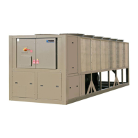
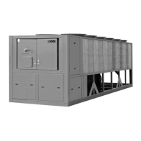
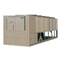
SHOWN WITH OPTIONAL
SINGLE POINT POWER CONNECTION

Questions and Answers:

York RecipPak YEAJ66HT9 Specifications

General IconGeneral
ModelYEAJ66HT9
Cooling Capacity66 Tons
Compressor TypeReciprocating
Number of Circuits2
CategoryChiller
Voltage460V
Operating Temperature Range115°F

Summary

GENERAL INFORMATION

UNIT NOMENCLATURE

Explains the structure and meaning of the chiller model number.

COMPRESSOR NOMENCLATURE

Z MODELS

Details the nomenclature for Z model compressors.

J MODELS

Details the nomenclature for J model compressors.

OPERATIONAL LIMITATIONS

VOLTAGE LIMITATIONS

Specifies the acceptable voltage ranges for safe chiller operation.

TEMPERATURES AND FLOWS

Lists temperature and flow parameters for various chiller models.

DIMENSIONS

ELECTRICAL DATA

WIRING DIAGRAMS

INSTALLATION

INSTALLATION CHECK LIST

A checklist of essential steps before placing units into operation.

LOCATION AND CLEARANCES

Guidelines for selecting an appropriate installation site and necessary clearances.

FOUNDATION

Requirements for a stable and level foundation for unit placement.

CHILLED LIQUID PIPING

CONNECTION DIAGRAM (SYSTEM WIRING)

UNIT CONTROLS AND OPERATION

INTRODUCTION

Overview of the microprocessor control system's capabilities and features.

MICROPROCESSOR BOARD

Details the function and operation of the central control unit.

"DISPLAY" KEYS

Chilled Liquid Temps

Shows chiller leaving and return water temperatures.

Ambient Temp

Shows the current outdoor ambient air temperature.

OPTIONS

TABLE 1 – SWITCH POSITION AND DISPLAY

SWITCH 1, SWITCH 4, SWITCH 2, SWITCH 5, SWITCH 3, SWITCH 6

"STATUS" KEY

UNIT SWITCH IS IN THE OFF POSITION

Indicates the main unit ON/OFF switch is in the OFF position.

DAILY SCHEDULE SHUTDOWN

Informs that the chiller is not running due to the programmed daily schedule.

CHILLER FAULTS, SYSTEM FAULTS

"ENTRY" KEYS

Numerical Keypad

Details the numerical keypad used for programming values.

"PROGRAM" KEY

DISCHARGE CUT-OUT

Sets a backup for the mechanical high pressure cut-out.

SUCTION PRESSURE CUT-OUT

"CLOCK" KEYS

Set Time

Programs the system clock, date, and time.

SELECTION OF RETURN OR LEAVING CHILLED LIQUID CONTROL

GENERAL

Mode selection overview for water temperature control.

PROGRAMMING RETURN WATER CONTROL

Chilled Liquid Temp/Range

Sets the desired chilled liquid temperature and its acceptable control range.

PROGRAMMING RETURN WATER RATE CONTROL

PROGRAMMING LEAVING WATER CONTROL

RATE CONTROL TEMP

RATE SENSITIVITY

FIG. 15 – 5 STEP LOADING/UNLOADING (RETURN WATER CONTROL)

LOADING AND UNLOADING LEAVING WATER TEMPERATURE CONTROL

"SYSTEM SAFETIES"

MANUAL RESET SAFETIES

Details safeties that shut down the system and require manual reset.

Motor Current Safety

Protects the motor from damage due to low or high current conditions.

Suction Pressure Safety

Prevents operation under low refrigerant conditions to avoid evaporator freeze-up.

Oil Pressure Safety

Discharge Pressure Safety

Pumpdown Safety

AUTOMATIC RESET SAFETIES

Low Water Temperature Safety

Protects the evaporator from freezing by monitoring chilled liquid temperature.

High Ambient Temperature Safety

Shuts down the chiller if ambient temperature exceeds operational limits.

Flow Switch

Monitors water flow to prevent evaporator freeze-ups.

INTERNAL TIMERS AND PUMPDOWN CONTROLS

ANTI-RECYCLE TIMER

Sets the minimum time before a compressor can restart after shutdown.

"PRINT" KEYS

REMOTE PRINTOUT

Obtains printouts of system data or fault history.

LOCAL DISPLAY READOUT

Oper Data

Provides access to real-time system operating data for monitoring.

"UNIT" ON / OFF SWITCH

UNIT ON/OFF SWITCH

Controls the overall operation of the chiller unit.

SYSTEM SWITCHES

Allows selective activation or deactivation of individual refrigerant systems.

LEAD/LAG COMPRESSOR SELECTION

MEMORY BATTERY BACK-UP

EMS/BAS CONTROLS

REMOTE START/STOP BY A CYCLING DEVICE OR TIME CLOCK

Details how to remotely start or stop the chiller using external devices.

REMOTE SETPOINT RESET (REMOTE RESET TEMP RANGE)

Allows remote adjustment of the water temperature setpoint.

FAN CONTROL STRATEGY ABOVE 25°F AMBIENT

COMPRESSOR CAPACITY CONTROL

“Z” COMPRESSOR (STYLE B) LOADING/UNLOADING

"J" COMPRESSOR (STYLE G) LOADING/UNLOADING

SYSTEM START-UP CHECKLIST

CHECKING THE SYSTEM 24 HOURS PRIOR TO INITIAL START-UP (NO POWER)

Pre-start checks for unit, piping, and electrical connections.

INITIAL START-UP

CHILLED LIQUID TEMPERATURES

Parameters for recording chilled liquid temperatures during start-up.

CHECKING SUPERHEAT AND SUBCOOLING

OPERATING SEQUENCE

PREVENTATIVE MAINTENANCE

DAILY MAINTENANCE

Recommended daily checks for oil level, pressure, and superheat.

ANNUAL MAINTENANCE

Annual checks including controls, oil, and refrigerant circuits.

OPTIONS

CONDENSER WATER PUMP CONTACT/RUN STATUS OPTION

Option to control condenser water pump or indicate run status.

EVAPORATOR WATER PUMP CONTACT OPTION

0°F LOW AMBIENT OPTION

Operation

How the low ambient option reduces condenser capacity for cold weather operation.

Programming

Ambient and Pressure Fan Control 0°F - 25°F

Fan control strategy for ambient temperatures between 0°F and 25°F.

Ambient and Pressure Fan Control 25° - 45°F

Pressure Control Only, Fan Control by Discharge Pressure

HOT GAS BYPASS (LOADMINDER) OPTION

General

Explains the purpose of the hot gas bypass option for load management.

LWT Control Hot Gas Operation

How hot gas bypass functions with leaving water temperature control.

FIELD INSTALLATION

HIGH AMBIENT OPTION

Details the components and operation of the high ambient option.

LOCAL PRINTER OPTION

Installation Limitations

Printer Configuration

OPTIONAL TAMPERPROOF ENCLOSURE (WIRE GRILLE)

General

Describes the purpose and components of the wire grille enclosure.

Installation

Instructions for installing the wire grille tamperproof enclosure.

OPTIONAL DECORATIVE TAMPERPROOF ENCLOSURE (LOUVERED & WIRE GRILLE)

General

Describes the decorative/tamperproof enclosure with louvers and grilles.

Installation

Instructions for installing the louvered and wire grille enclosure.

OPTIONAL DECORATIVE TAMPERPROOF ENCLOSURE (LOUVERED)

General

Describes the decorative/tamperproof enclosure with louvers.

Installation

Instructions for installing the louvered enclosure.

BAS INTERFACE OPTION (REMOTE RESET OPTION)

0-10VDC

Wiring and programming for 0-10VDC remote temperature setpoint offset.

4-20mA

Wiring and programming for 4-20mA remote temperature setpoint offset.

Dry Contact

Wiring and programming for dry contact remote temperature setpoint offset.

TROUBLESHOOTING CHART

No display on panel Unit will not operate

Troubleshooting steps for when the unit fails to power on or display any information.

"Low Suction" Fault

"High Dsch" Fault

"Chiller Fault: Low Water Temp"

Compressor won't load

Related product manuals