EasyManua.ls Logo

York RecipPak YEAJ77MT9 User Manual

York RecipPak YEAJ77MT9
92 pages
To Next Page IconTo Next Page
Page #1 background imageLoading...
Page #1 background image
INSTALL., OPER., MAINT.
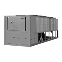
RecipPak LIQUID CHILLERS
AIR COOLED – RECIPROCATING HERMETIC
Supersedes: See Back Page
Form 150.60-NM4 (1095)
60 HZ MODELS
YEAZ88DR6, YEAJ44DR6, YEAJ44HT6, YEAJ54ES6,
YEAJ55HT8, YEAJ65HT8, YEAJ66MT8
50 HZ MODELS
YEAJ44DR7, YEAJ55DR7, YEAJ55HT7, YEAJ65ES7,
YEAJ66HT9, YEAJ76HT9, YEAJ77MT9
STYLE A*
*With EPROM 031-01096-001 (Standard, Brine & Metric Models, Combined)
200, 230, 460-3-60
®
M
A
N
U
F
A
C
T
U
R
E
R
C
E
R
T
I
F
I
E
D
T
O
A
R
I
A
S
C
O
M
P
L
Y
I
N
G
W
I
T
H
A
R
I
S
T
A
N
D
A
R
D
4
3
0
C
E
N
T
R
A
L
S
T
A
T
I
O
N
A
I
R
-
H
A
N
D
L
I
N
G
U
N
I
T
S
26174A
SHOWN WITH OPTIONAL
SINGLE POINT POWER CONNECTION

Questions and Answers:

York RecipPak YEAJ77MT9 Specifications

General IconGeneral
ModelYEAJ77MT9
CategoryChiller
Cooling Capacity77 Tons
Refrigerant TypeR-134a
Compressor TypeReciprocating
Width48 in
Voltage460V
Sound Power Level85 dB

Summary

General Information

General Description

Provides a general overview of the packaged liquid chillers and their intended applications.

Code Status

Details the codes and standards (UL, NEC, ASHRAE/ANSI, ASME) to which the units are designed.

Unit Nomenclature

Explains the structure and meaning of the unit model number components.

Compressor Nomenclature

Z Models

Details the nomenclature structure for Z model compressors, including series, displacement, and motor size.

J Models

Details the nomenclature structure for J model compressors, including series, style, stroke, and motor size.

Operational Limitations

Voltage Limitations

Specifies absolute and operational voltage limitations to prevent serious damage to the compressor.

Temperatures and Flows

Provides minimum and maximum operating temperatures and flow rates for various chiller models.

Dimensions

Physical Data

Electrical Data

Installation

Installation Check List

Outlines essential pre-operation checks, including shipping damage, piping, and limitations verification.

Handling

Provides guidelines for safely lifting and moving the assembled chiller units to prevent damage.

Inspection

Details the process for inspecting the unit upon receipt for transit damage and reporting it.

Location and Clearances

Advises on selecting an outdoor location for minimum sun exposure and adequate condenser airflow.

Foundation

Specifies requirements for a flat, level foundation capable of supporting the unit's operating weight.

Wiring Diagrams

Connection Diagram (System Wiring)

Compressors

Illustrates wiring connections for compressor terminal boxes, showing details for Z and J compressor types.

Connection Diagram, Electrical Box

Unit Controls and Operation

Introduction

Introduces the York MicroComputer Control Center as a microprocessor-based system for multi-circuit chiller control.

Microprocessor Board

Describes the role of the Microprocessor Board as the controller and decision-maker in the system.

"Display" Keys

General

Explains how to use DISPLAY keys to retrieve system operating data for monitoring and troubleshooting.

Chilled Liquid Temps

Describes the display output for chiller leaving and return water temperatures.

System 1 Pressures

Explains how to view oil, suction, and discharge pressures for System 1.

DIP Switch Configuration

Switch 1

Configures chiller control mode (Comfort Cooling vs. Brine & Process Duty) and affects temperature setpoint range.

Switch 4

Selects between Return Water Control and Leaving Water Control for chiller operation.

Switch 2

Sets the low ambient cut-out behavior, either fixed at 25°F or programmable from 0-50°F.

Switch 5

Determines whether display messages use English or Metric units of measurement.

Switch 3

Selects between Local Control Mode and Remote Control Mode for chiller operation.

Switch 6

Configures condenser fan control, either Standard or Shared, based on chiller fan configuration.

Switch 7

Configures compressor lead/lag operation, either Manual or Automatic.

Switch 8

Sets fan control strategy based on ambient temperature and discharge pressure.

"Status" Key

General

Explains how the STATUS key allows operators to view current chiller operating status and fault conditions.

General Status Messages

Describes various general status messages displayed, indicating unit/system operation or state.

"Entry" Keys

General

Explains the function of the ENTRY key for changing programmed numerical values like setpoints and clock settings.

Numerical Keypad

Details the keys on the numerical keypad used for programming numerical values.

Enter Key

Describes the function of the ENTER key for accepting programmed changes and scrolling through data.

Cancel Key

Explains how the CANCEL key is used to correct errors during data programming.

"Program" Key

General

Describes how the PROGRAM key allows users to program operating limits, safeties, and timers.

Discharge Cut-Out

Details the function and programming of the discharge cut-out as a backup for the mechanical high pressure cut-out.

"Program" Key Settings

Suction Pressure Unload

Explains the suction pressure unload point, used to ensure adequate compressor cooling by reducing motor heating.

Anti Recycle Time

Allows selection of compressor anti-recycle time to prevent motor damage from frequent starts.

"Program" Key Settings Continued

Rate Sensitivity

Defines the rate of water temperature change that triggers micro-response, affecting loading/unloading.

Number of Load Steps

Specifies the number of stages for compressor loading/unloading, essential for proper sequencing.

"Clock" Keys

General

Explains the CLOCK feature for monitoring time, day, and date, enabling automatic chiller start/stop schedules.

Set Time

Details the procedure for programming the current day, time, and date into the chiller's internal clock.

"Clock" Keys Programming

Programming the Daily Start/Stop and Holiday Schedule

Guides on setting daily start/stop times and programming special schedules for holidays.

Selection of Return or Leaving Chilled Liquid Control

General

Explains the user's ability to select between Return Water Control and Leaving Water Control for fine-tuning cooling methods.

Manual Override

Describes the function of the MANUAL OVERRIDE key for emergency or servicing operations.

"Setpoints" Keys

General

Explains how to program chilled liquid setpoints and remote reset temperature ranges after selecting control mode.

Programming Return Water Control

Details how to program setpoints and control ranges when using Return Water Control mode.

Chilled Liquid Temp/Range

Guides on setting the desired chilled liquid temperature and the allowable control range.

"Setpoints" Keys Continued

Programming Leaving Water Control

Details how to program setpoints and control ranges for Leaving Water Control mode.

Loading and Unloading

Return Water Temperature Control

Explains how loading/unloading operates in RWT control to maintain leaving water temperature via return water feedback.

Loading and Unloading Continued

Leaving Water Temperature Control

Describes how loading/unloading functions in LWT control to maintain precise leaving water temperatures.

"System Safeties"

Manual Reset Safeties

Explains safeties that shut down the system upon exceeding thresholds, requiring manual intervention to reset.

Motor Current Safety

Monitors motor current to prevent damage from low or high current conditions.

Suction Pressure Safety

Assures the system does not run under low refrigerant conditions or other flow-inhibiting problems.

"System Safeties" Continued

Oil Pressure Safety

Ensures proper compressor lubrication by monitoring oil pressure levels.

Discharge Pressure Safety

Prevents excessive system pressure that could cause relief valve activation and refrigerant loss.

Pumpdown Safety

Ensures the compressor performs a proper pumpdown cycle before refrigerant flow starts, preventing liquid slugging.

Motor Protector

Describes the function of the motor protector module that senses motor winding temperature and de-energizes the contactor.

"System Safeties" Continued Further

Automatic Reset Safeties

Explains safeties that automatically shut down the chiller on a fault and allow automatic restart after the condition clears.

Low Water Temperature Safety

Protects the evaporator from freezing by shutting down the chiller if chilled liquid temperature drops below a set point.

High Ambient Temperature Safety

Prevents chiller operation in excessively high ambient temperatures to avoid potential component malfunction.

Under Voltage Safety

Protects the microprocessor from damage due to low system voltages.

"System Safeties" Continued Even Further

Power Failure Safety

Manages auto-restart after power interruptions, ensuring minimum motor cooling time.

Anticipation Safety Controls

Overrides temperature controls to prevent shutdowns by automatically adjusting system loading based on pressure thresholds.

Suction Pressure Unloading

Unloads the compressor if suction pressure rises above a programmed limit to ensure proper compressor cooling.

Discharge Pressure Unloading

Unloads the compressor if discharge pressure exceeds a programmed limit to prevent high pressure cut-outs.

"Print" Keys

Remote Printout

Explains how to obtain printouts of real-time data or fault history for remote printers.

Oper Data

Allows remote retrieval of current system operating parameters and panel programming selections.

History

Enables remote printing of information related to the last three safety shutdowns and system conditions at the time of fault.

Local Display Readout

Oper Data

Allows scrolling through additional real-time system data not available via standard DISPLAY keys.

"Unit" On / Off Switch

Unit On/Off Switch

Describes the master rocker switch that controls the overall chiller operation, turning it ON or OFF.

System Switches

Explains the function of system switches on the microprocessor board for selectively enabling/disabling individual refrigerant systems.

Alarm Contacts (Annunciation Alarm)

Details the dry contacts used for external alarm annunciation triggered by faults or power loss.

Memory Battery Back-Up

EMS/BAS Controls

Remote Start/Stop by a Cycling Device or Time Clock

Explains how to connect external devices for remote chiller start and stop control.

Remote Setpoint Reset (Remote Reset Temp Range)

Details how to remotely adjust the chiller's setpoint upwards using a dry contact or voltage/current signal.

EMS/BAS Controls Continued

Remote Unloading

Describes how to remotely shut down the lag compressor or unload the lead compressor to minimum capacity.

Fan Control Strategy

Above 25°F Ambient

Describes standard fan cycling strategy based on outdoor ambient temperature above 25°F.

For operation below 25°F

Notes the requirement for a Low Ambient Kit for operation below 25°F and refers to specific page for details.

Compressor Capacity Control

"Z" Compressor (Style B) Loading/Unloading

"J" Compressor (Style G) Loading/Unloading

System Start-Up Checklist

Checking the System 24 Hours Prior to Initial Start-Up (No Power)

Lists pre-start checks for unit, piping, charge, valves, and general inspection.

Panel Checks (Power On-Both System Switches "Off")

Details checks to be performed on the control panel after applying power, including voltage verification and heater status.

Checking Superheat and Subcooling

Operating Sequence

Preventative Maintenance

Daily Maintenance

Recommends daily checks for oil level, oil pressure, compressor superheat, and operating pressures/temperatures.

Weekly Maintenance

Recommends weekly checks including daily items, compressor oil color, and refrigerant circuit leak checks.

Annual Maintenance

Outlines annual tasks, including checking controls, draining/refilling compressor oil, and inspecting for wear.

Options

Condenser Water Pump/Run Status Contact Option

Describes an option providing a dry contact to control condenser water pumps or indicate run status.

Options Continued

Evaporator Water Pump Contact Option

Details an option providing a dry contact to control the evaporator water pump based on compressor status or schedule.

0°F Low Ambient Option

Explains the Low Ambient Option for chiller operation in ambients between 0°F and 25°F, involving fan cycling and discharge pressure control.

Ambient and Pressure Fan Control 25° - 45°F

Ambient and Pressure Fan Control 45°F and Higher

Pressure Control Only, Fan Control by Discharge Pressure

Hot Gas Bypass (Loadminder) Option

General

Introduces the Hot Gas Bypass Option for preventing compressor cycling and water temperature fluctuation at low loads.

LWT Control Hot Gas Operation

Explains how hot gas bypass operates when the chiller is in Leaving Water Temperature Control mode.

RWT Control Hot Gas Operation

Explains how hot gas bypass operates when the chiller is in Return Water Temperature Control mode.

Procedure For Setting The Hot Gas Regulator

Guides on setting the hot gas regulator valve adjustment for proper operation.

Hot Gas Bypass (Loadminder) Option Continued

Field Installation

Provides information on kits required for field installation of the Hot Gas Bypass Option.

High Ambient Option

Details the components and function of the High Ambient Option, allowing operation up to 115°F.

Local Printer Option

Optional Tamperproof Enclosure (Wire Grille)

General

Describes the wire grille enclosure for deterring unauthorized access to chiller components.

Installation

Provides instructions and refers to figures/parts lists for installing the wire grille enclosure.

Optional Decorative Tamperproof Enclosure (Louvered & Wire Grille)

General

Describes the decorative enclosure combining louvered panels and wire grilles for deterring access and enhancing appearance.

Installation

Provides instructions and refers to figures/parts lists for installing the louvered & wire grille enclosure.

Optional Decorative Tamperproof Enclosure (Louvered)

General

Describes the decorative louvered enclosure made of sheet metal panels for deterring unauthorized access and improving appearance.

Installation

Provides instructions and refers to figures/parts lists for installing the louvered enclosure.

BAS Interface Option (Remote Reset Option)

0-10VDC

Details the setup for using a 0-10VDC signal for remote temperature setpoint adjustment.

4-20mA

Details the setup for using a 4-20mA signal for remote temperature setpoint adjustment.

Dry Contact

Explains how to use a dry contact for offsetting temperature, requiring potentiometer adjustment.

Troubleshooting Chart

Related product manuals