EasyManua.ls Logo

York RecipPak YEAJ55DR7 - User Manual

York RecipPak YEAJ55DR7
92 pages
To Next Page IconTo Next Page
Loading...
INSTALL., OPER., MAINT.
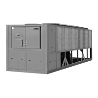
RecipPak LIQUID CHILLERS
AIR COOLED – RECIPROCATING HERMETIC
Supersedes: See Back Page
Form 150.60-NM4 (1095)
60 HZ MODELS
YEAZ88DR6, YEAJ44DR6, YEAJ44HT6, YEAJ54ES6,
YEAJ55HT8, YEAJ65HT8, YEAJ66MT8
50 HZ MODELS
YEAJ44DR7, YEAJ55DR7, YEAJ55HT7, YEAJ65ES7,
YEAJ66HT9, YEAJ76HT9, YEAJ77MT9
STYLE A*
*With EPROM 031-01096-001 (Standard, Brine & Metric Models, Combined)
200, 230, 460-3-60
®
M
A
N
U
F
A
C
T
U
R
E
R
C
E
R
T
I
F
I
E
D
T
O
A
R
I
A
S
C
O
M
P
L
Y
I
N
G
W
I
T
H
A
R
I
S
T
A
N
D
A
R
D
4
3
0
C
E
N
T
R
A
L
S
T
A
T
I
O
N
A
I
R
-
H
A
N
D
L
I
N
G
U
N
I
T
S
26174A
SHOWN WITH OPTIONAL
SINGLE POINT POWER CONNECTION

Questions and Answers:

York RecipPak YEAJ55DR7 Specifications

General IconGeneral
BrandYork
ModelRecipPak YEAJ55DR7
CategoryChiller
LanguageEnglish

Summary

GENERAL INFORMATION

General Description

Provides a general overview of the packaged liquid chillers.

Code Status

Details compliance with industry standards and codes.

Unit Nomenclature

Explains the breakdown and meaning of the unit's model number.

COMPRESSOR NOMENCLATURE

Z Models

Explains the nomenclature for Z series compressors.

J Models

Explains the nomenclature for J series compressors.

OPERATIONAL LIMITATIONS

Voltage Limitations

Specifies voltage ranges for safe operation and to prevent damage.

Temperatures and Flows

Lists temperature and flow limits for various models.

DIMENSIONS

Weight Distributions (LBS.)

Provides weight distribution data for different models and configurations.

Nozzle Size Inlet;Outlet

Specifies the inlet and outlet nozzle sizes for each model.

ELECTRICAL DATA

WIRING DIAGRAMS

Dual Compressor Power Supply Wiring Standard Unit

Illustrates the standard wiring for dual compressor power supply.

Single Point Wiring (Optional)

Details wiring for the optional single point connection.

Single Point Wiring with Unit Mounted Disconnect Switch (Optional)

Shows wiring for single point connection with an optional disconnect.

INSTALLATION

Installation Check List

Lists essential checks before unit operation.

Handling

Provides instructions for safely moving and handling the unit.

Inspection

Details steps for inspecting the unit upon receiving it.

Location and Clearances

Specifies requirements for unit placement and surrounding space.

Ground Level Locations

Shipping Braces

Instructions for removing shipping brackets before mounting.

Spring Isolators (Optional)

Details installation of optional spring vibration isolators.

Rooftop Locations

COMPRESSOR MOUNTING

Chilled Liquid Piping

Provides general guidelines for connecting chilled liquid piping systems.

ELECTRICAL WIRING

Field Wiring

Details requirements for connecting external power and control wiring.

WIRING DIAGRAMS

Dual Compressor Power Supply Wiring Standard Unit

Illustrates the standard wiring for dual compressor power supply.

Single Point Wiring (Optional)

Details wiring for the optional single point connection.

Single Point Wiring with Unit Mounted Disconnect Switch (Optional)

Shows wiring for single point connection with an optional disconnect.

CONTROL POWER SUPPLY

Control Circuit

Details the schematic for the control circuit.

CONNECTION DIAGRAM (SYSTEM WIRING)

6 Cyl. Z Compressor Wiring

Shows wiring connections for "Z" compressor models.

4 & 6 Cyl. J Compressor Wiring

Shows wiring connections for "J" compressor models.

COMPRESSOR TERMINAL BOX (SYSTEM NO. 1)

4 Cyl. J Compressor Wiring

Wiring details for 4-cylinder "J" compressors, System 1.

6 Cyl. J Compressor Wiring

Wiring details for 6-cylinder "J" compressors, System 1.

COMPRESSOR TERMINAL BOX (SYSTEM NO. 2)

4 Cyl. J Compressor Wiring

Wiring details for 4-cylinder "J" compressors, System 2.

6 Cyl. J Compressor Wiring

Wiring details for 6-cylinder "J" compressors, System 2.

UNIT CONTROLS AND OPERATION

Microprocessor Board

Explains the role of the microprocessor board as the main controller.

Power Supply Board

Describes the function of the power supply board.

Relay Output Board

Explains how the relay output board converts logic to AC levels.

Keypad

Explains the operator keypad for system control.

“DISPLAY” KEYS

General Explanation

Explains the purpose and function of the DISPLAY keys.

Chilled Liquid Temps Display

Describes how to display chiller leaving and return water temperatures.

System 1 Pressures Display

Details how to display System 1 oil, suction, and discharge pressures.

System 2 Pressures Display

Details how to display System 2 oil, suction, and discharge pressures.

DIP SWITCH SETTINGS AND OPERATION

Cooling and Ambient Control Modes

Explains Switch 1 and Switch 2 settings for cooling and ambient control.

Control Mode and Water Temperature Selection

Explains Switch 3 and Switch 4 settings for control mode and water temperature.

DIP SWITCH SETTINGS AND OPERATION (Cont.)

Switch 7: Lead;Lag Compressor Selection

Explains Switch 7 OPEN for manual lead/lag control.

Switch 8: Fan Control Strategy

Explains Switch 8 OPEN for ambient/discharge pressure fan control.

“STATUS” KEY

General Explanation

Explains how to use the STATUS key to view chiller operating status.

General Status Messages

Discusses general status messages displayed by the system.

Unit Switch Off Position

Informs the operator the unit is OFF.

“ENTRY” KEYS

General Explanation

Explains the purpose of ENTRY keys for changing values.

Numerical Keypad

Describes the numerical keypad for inputting values.

Enter Key Function

Explains the ENTER key's function to accept input.

Cancel Key Function

Explains the CANCEL key for correcting errors.

“PROGRAM” KEY

Programming User Programmable Safeties and Limits

Guides users on programming safeties and operational limits.

Discharge Cut-Out Programming

Details how to program the discharge pressure cut-out setting.

PROGRAMMING SETTINGS (Cont.)

Ambient Temperature Cut-Outs

Combines High and Low Ambient temperature cut-out programming.

Discharge Pressure Unload

Details programming the discharge pressure unload point.

PROGRAMMING SETTINGS (Cont.)

Suction Pressure Unload and Anti Recycle Time

Details programming for suction unload and anti-recycle timers.

Rate Control Temp and Leaving Water Cut-Out

Details programming for rate control temperature and leaving water cut-out.

PROGRAMMING SETTINGS (Cont.)

Suction Pressure Cut-Out

Details programming the suction pressure cut-out setting.

Rate Sensitivity

Explains setting the rate sensitivity parameter.

Number of Load Steps

Explains programming the number of compressor unloading steps.

“CLOCK” KEYS

Programming Day, Time, and Date

Guides on setting the system clock, date, and time.

Set Time Procedure

Details the process for setting the system time and date.

“CLOCK” KEYS (Cont.)

Programming Daily Start;Stop and Holiday Schedule

Guides on programming daily and holiday start/stop schedules.

Set Schedule;Holiday Procedure

Guides on programming daily and holiday start/stop schedules.

SELECTION OF RETURN OR LEAVING CHILLED LIQUID CONTROL

General Discussion

Discusses selecting between return and leaving chilled liquid control.

Return Water Control Selection

Details switch settings for Return Water Control.

Leaving Water Control Selection

Details switch settings for Leaving Water Control.

“SETPOINTS” KEYS

Programming Chilled Liquid Setpoints and Remote Reset

Guides on programming setpoints and remote reset ranges.

Programming Return Water Control

Details programming for return water control.

Chilled Liquid Temp;Range Programming

Explains how to set chilled liquid temperature and range.

PROGRAMMING SETTINGS (Cont.)

Programming Leaving Water Rate Control

Guides on programming leaving water rate control parameters.

PROGRAMMING SETTINGS (Cont.)

Programming Leaving Water Rate Control

Guides on programming leaving water rate control parameters.

Programming Return Water Rate Control

Details programming for return water rate control.

Rate Control Temp Setting

Explains setting the rate control temperature parameter.

PROGRAMMING SETTINGS (Cont.)

Programming Leaving Water Control

Guides on programming leaving water control parameters.

Chilled Liquid Temp;Range for Leaving Water Control

Explains setting chilled liquid temp/range for leaving water control.

PROGRAMMING SETTINGS (Cont.)

Low-Limit Water Temperature (LWT) Programming

Details setting the low-limit water temperature.

PROGRAMMING SETTINGS (Cont.)

Programming Leaving Water Rate Control

Guides on programming leaving water rate control.

Rate Sensitivity Setting

Explains setting the rate sensitivity parameter.

LOADING AND UNLOADING

Return Water Temperature Control

Explains loading/unloading in return water temperature control.

LOADING AND UNLOADING (Cont.)

Leaving Water Temperature Control

Explains loading/unloading in leaving water temperature control.

“SYSTEM SAFETIES”

Manual Reset Safeties

Explains safety shutdowns requiring manual reset.

Motor Current Safety

Details safety against low or high motor current.

Suction Pressure Safety

Explains safety for low refrigerant conditions or flow problems.

“SYSTEM SAFETIES” (Cont.)

Oil Pressure Safety

Details safety related to oil pressure.

Discharge Pressure Safety

Details safety related to discharge pressure.

Pumpdown and Compressor Protection

Covers pumpdown safety and compressor protection safeties.

AUTOMATIC RESET SAFETIES

Low Water and Ambient Temperature Safeties

Covers low water and ambient temperature automatic reset safeties.

Under Voltage and Flow Switch Safeties

Covers under voltage and flow switch automatic reset safeties.

SYSTEM OPERATION AND TIMERS

Power Failure and Anticipation Safeties

Covers power failure safety and anticipation controls.

Pressure Unloading Controls

Details suction and discharge pressure unloading controls.

Internal Timers and Pumpdown

Explains anti-recycle timer, anti-coincidence timer, and pumpdown.

“PRINT” KEYS

Remote Printout Operations

Explains obtaining printouts of operating data and fault history.

LOCAL DISPLAY READOUT

Oper Data Readouts

Explains retrieving additional real-time display information.

OPERATIONAL STATUS INDICATORS

Load and Unload Timers

Displays real-time load and unload timer values.

Temperature Demand and Rate

Informs operator about loading stage and temp change rate.

System Lead and Pump Status

Indicates lead system, pump, and heater status.

OPERATIONAL STATUS INDICATORS (Cont.)

Condenser Water Pump Status

Informs if the condenser water pump is commanded ON.

History and Fault Review

Allows scrolling through safety shutdown buffers for fault analysis.

FAULT DATA DETAILS

Lead System and Control Type

Shows lead system and control type at fault time.

Water Temperature and Pressure Data

Displays water temps and pressures at fault time.

Compressor and Fan Status

Shows compressor and fan status at fault time.

FAULT DATA DETAILS (Cont.)

System 1 Reverse Fans and Hot Gas Valve

Shows SYS 1 fan and hot gas valve status at fault time.

System 2 Compressor, Loading Stages, and Fans

Shows SYS 2 compressor, stages, and fan status at fault time.

System 2 Pressure and Oil Data

Shows SYS 2 pressure and oil data at fault time.

UNIT AND SYSTEM CONTROL

Unit and System On;Off Switches

Explains the master switch and system switches for chiller operation.

Alarm Contacts and Lead;Lag Selection

Covers alarm contacts and lead/lag compressor selection.

SYSTEM COMPONENTS AND MAINTENANCE

Memory Battery Back-Up

Explains the microprocessor board's memory battery back-up.

Clock Jumper Settings

Explains the jumper for controlling the clock's power.

SYSTEM OPTIONS AND CONTROLS

Heaters and Display Options

Covers crankcase heater, evaporator heater, and metric display options.

EMS;BAS Controls

Discusses interface options for EMS/BAS systems.

SYSTEM OPTIONS AND CONTROLS (Cont.)

Remote Unloading

Explains remote unloading and pulldown demand limiting.

FAN CONTROL STRATEGY

Above 25°F Ambient Fan Control

Details fan control strategy above 25°F ambient temperature.

COMPRESSOR CAPACITY CONTROL

COMPRESSOR LOADING;UNLOADING

Z Compressor Loading;Unloading

Explains loading/unloading for "Z" compressors.

J Compressor Loading;Unloading

Explains loading/unloading for "J" compressors.

SYSTEM START-UP CHECKLIST

Pre-Start Checks (No Power)

Lists pre-start checks before applying power.

Panel Checks (Power On)

Details checks to be performed with power on but systems off.

INITIAL START-UP

System Switch Activation

Instructs to turn system switches ON for operation.

CHECKING SUPERHEAT AND SUBCOOLING

Subcooling Check

Details how to check and set subcooling levels.

Superheat Check

Details how to check and set superheat levels.

OPERATING SEQUENCE

PREVENTATIVE MAINTENANCE

Daily Maintenance

Lists daily checks for system maintenance.

Weekly Maintenance

Lists weekly checks for system maintenance.

Annual Maintenance

Lists annual checks and procedures for maintenance.

OPTIONS

Condenser Water Pump Contact;Run Status Option

Explains the condenser water pump contact option.

OPTIONS (Cont.)

Evaporator Water Pump Contact Option

Explains the evaporator water pump contact option.

0°F Low Ambient Option Operation

Explains how the low ambient option reduces condenser capacity.

LOW AMBIENT OPTION

Ambient and Pressure Fan Control (0°F - 25°F)

Details fan control strategy below 25°F ambient.

Fan Control Strategy (Below 25°F)

Explains fan control strategy below 25°F ambient.

FAN CONTROL STRATEGIES

Ambient and Pressure Fan Control (25° - 45°F)

Details fan control strategy between 25°F and 45°F.

Ambient and Pressure Fan Control (45°F and Higher)

Details fan control strategy above 45°F.

Pressure Control Only Fan Control

Explains fan control based solely on discharge pressure.

HOT GAS BYPASS (LOADMINDER) OPTION

General Description and Operation Modes

Covers general description, LWT and RWT hot gas operations.

Setting the Hot Gas Regulator

Provides procedure for setting the hot gas regulator.

FIELD INSTALLATION AND OPTIONS

Hot Gas Bypass (Loadminder) Field Installation

Details field installation procedures for the hot gas bypass option.

Discharge Pressure Readout Option

Explains the discharge pressure readout option.

High Ambient Option

Details the high ambient option for operation up to 115°F.

LOCAL PRINTER OPTION

PRINTER INSTALLATION AND OPERATION

Installation Limitations

Lists limitations for printer installation.

Obtaining a Print-out

Explains how to obtain printouts of operating data and fault history.

Using Other Printers

Discusses using printers other than the recommended model.

OPTIONAL TAMPERPROOF ENCLOSURE

Wire Grille Enclosure General

Describes the wire grille enclosure for deterring access.

Wire Grille Enclosure Installation

Provides instructions for installing the wire grille enclosure.

OPTIONAL DECORATIVE TAMPERPROOF ENCLOSURE

Louvered & Wire Grille Enclosure General

Describes the louvered and wire grille enclosure.

Louvered & Wire Grille Enclosure Installation

Provides instructions for installing the enclosure.

OPTIONAL DECORATIVE TAMPERPROOF ENCLOSURE (LOUVERED)

Louvered Enclosure General

Describes the louvered enclosure for deterring access.

Louvered Enclosure Installation

Provides instructions for installing the louvered enclosure.

BAS INTERFACE OPTION (REMOTE RESET OPTION)

0-10 VDC Signal Connection

Details 0-10VDC signal connection for remote reset.

4-20 mA Signal Connection

Details 4-20mA signal connection for remote reset.

Dry Contact Connection

Explains dry contact connection for offset temperature.

TROUBLESHOOTING CHART

TROUBLESHOOTING CHART (Cont.)

TROUBLESHOOTING CHART (Cont.)

TROUBLESHOOTING CHART (Cont.)

Related product manuals