Do you have a question about the York VSD 270 and is the answer not in the manual?
Symbols used in the document to alert readers to specific situations like danger, warning, caution, and notes.
Information on how the document content is subject to change without notice.
Details revisions made to the document, including affected pages and descriptions of changes.
Lists related manual descriptions and their corresponding form numbers.
Details the Johnson Controls Conditioned Based Maintenance (CBM) program as an alternative to traditional maintenance.
Explains the model nomenclature for VSD drives and provides a diagram for understanding part numbers.
Lists VSD model part numbers and their corresponding descriptions for various HP and VAC configurations.
Diagram and explanation of the nomenclature used for LVD models, including drive type, HP, and design center.
Lists LVD model part numbers and their descriptions for various HP and VAC configurations.
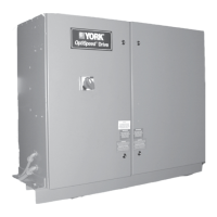
Overview of the OptiSpeed compressor drive's components, including the AC to DC rectifier and inverter sections.
Details the optional harmonic filter and high frequency trap designed to meet IEEE Std 519.
Explains the differences in design center nomenclature for G and W models, focusing on cooling system variations.
Compares VSD and LVD drives regarding harmonic filter system inclusion and enclosure size.
Describes how the OSCD control system connects to Microcomputer or OptiView Control Centers.
Details the components and functions of the Control Center and ACC board prior to 2005.
Explains the interconnection and functions of OSCD and Harmonic Filter logic boards.
Details related keypad functions for Microcomputer control panels and changes in displayed data.
Information regarding OptiView control panel VSD functions is contained within the Motor and Compressor Screens.
Describes the YORK OSCD's adaptive system for finding optimum speed and avoiding surge.
Diagram illustrating the system architecture of a VSD 351 model, similar to other models.
Image of the VSD logic board, typically located on the panel door.
Image of the SCR trigger board.
Explains how safety shutdowns are organized and the sequence of events when one occurs.
Lists safety shutdown messages, their descriptions, drive horsepower ratings, and threshold values.
Describes how cycling shutdowns are organized and the sequence of events when they occur.
Lists cycling shutdown messages, their descriptions, and associated conditions.
Explains that WARNING messages indicate affected operation but the OSCD is still functioning.
Lists warning messages, their descriptions, and the conditions under which they appear.
Provides conversion factors from English units to SI metric units for various measurements.
Instructions on how to convert Fahrenheit temperatures and temperature ranges to Celsius.