EasyManua.ls Logo

York YCSA 120 T User Manual

York YCSA 120 T
48 pages
To Next Page IconTo Next Page
Page #1 background imageLoading...
Page #1 background image
Technical Information
Air-condensed water chillers
and heat pumps
YCSA/YCSA-H 120 and 150 T and TP
(R-410A)
Ref.: Y-R70161 0707


E U R O V E N T
CERTIFIED PERFORMANCE
Johnson Controls Manufacturing España, S.L. is participating in the EUROVENT
Certification Program.
Products are as listed in the EUROVENT Directory of Certified Products, in the
program AC1, AC2, AC3, LCP and FC.
The LCP program covers air condensed water chillers and heat pumps of up
to 600 kW.
Question and Answer IconNeed help?

Do you have a question about the York YCSA 120 T and is the answer not in the manual?

York YCSA 120 T Specifications

General IconGeneral
BrandYork
ModelYCSA 120 T
CategoryAir Conditioner
LanguageEnglish

Summary

Technical Information

General Information

General Description

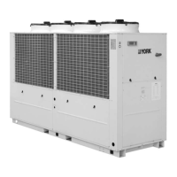
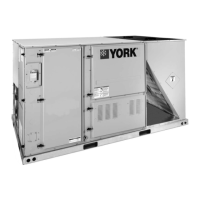
Overview of high-performance air-water chillers and heat pumps.

Models Available and Capacities

Details on available YCSA/YCSA-H models and their cooling/heating capacities.

Features and Advantages

Compressors

Description of hermetic scroll compressors and their operating features.

Electric and Control Panel

Details on the unit's control panel, including components and accessibility.

Physical Data: Cool Only Units

Physical Data: Heat Pump Units

Operation, Cooling and Hydraulic Diagram

Cool Only Unit YCSA 120/150

Diagram and explanation of the cooling cycle for cool only units.

Operation, Cooling and Hydraulic Diagram: Heat Pump Unit

Heat Pump Unit YCSA-H 120/150

Diagram and explanation of cooling and heating cycles for heat pump units.

Selection Guide for YCSA and YCSA-H

Necessary Information

Information required for selecting the appropriate YCSA/YCSA-H water chiller.

Selection Example

Illustrative example of selecting a YCSA-H heat pump based on design conditions.

Installation Instructions

Safety

Guidelines for safe installation and maintenance by qualified personnel.

Warning Signs

Explanation of safety symbols and their meanings found on the unit.

Wiring and Connections

Electrical Connections

Requirements for electrical connections according to national regulations.

Hydraulic Connections

Details on proper connection of water intake and outlet for the chiller.

Dimensions and Hydraulic Connections

Electrical Characteristics

Limits of Use

Operational voltage limits and temperature ranges for the units.

Operating Instructions: μC3 Control

Digital Inputs and Outputs

List and description of digital inputs/outputs for unit control and monitoring.

Control Module Components

Keyboard-Display

Description of the keyboard-display unit and its functions.

μC3 Controller

Description of the μC3 controller module and its connectivity.

General Wiring Diagram

Probe Configuration

Settings and Alarms

Alarm Settings

Parameters for configuring unit alarms, delays, and reset conditions.

Temperature Control

Settings for unit temperature control, compensation, and set points.

System Functions and Safety

Antifreeze Protection

Operation and parameters for preventing freezing in the unit.

Alarm System

How alarms are generated, displayed, and reset on the unit.

Alarm Table

Remote Control Unit

Connection to Control Panel

Diagram showing the wiring connection between the remote control and the control panel.

Related product manuals