EasyManua.ls Logo

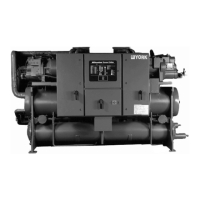
York YCWS0313SC User Manual

York YCWS0313SC
104 pages
To Next Page IconTo Next Page
Page #1 background imageLoading...
Page #1 background image
INSTALLATION, OPERATION AND
MAINTENANCE
YCWS
WATER COOLED LIQUID CHILLERS
New Release
Form 201.24-NM2 (601)
50 HERTZ
STYLE B
REFRIGERANT TYPE: R-22
00546VIP
YCWS WATER COOLED LIQUID CHILLERS
YCWS0313SC – 0663SC

Table of Contents

Questions and Answers:

York YCWS0313SC Specifications

General IconGeneral
BrandYork
ModelYCWS0313SC
CategoryChiller
LanguageEnglish

Summary

SECTION 1 SUPPLIER INFORMATION

Safety

Critical safety information and compliance standards.

Product Components and Controls

Microprocessor Controls

Features and functions of the main control system.

Control Features

Motor Protector Module

Details on overload, phase loss, and phase rotation protection.

SECTION 4 INSTALLATION

Installation Details (Cont.)

ELECTRICAL CONNECTION

Recommendations for safe electrical hookup.

Installation Details (Cont.)

POWER WIRING

Details on power supply requirements and connections.

SECTION 5 COMMISSIONING

Preparation

Initial checks before starting the unit.

FIRST TIME START-UP

Step-by-step procedure for initial unit startup.

SECTION 6 UNIT OPERATION

START-UP

Steps for starting the chiller unit.

Micropanel Controls

1.9 MOTOR PROTECTOR MODULES

Role of motor protector modules in system protection.

Micropanel Status Messages

Micropanel Status Messages (Cont.)

3.3 UNIT WARNINGS

Conditions requiring operator intervention or indicating extreme operating conditions.

3.6 SYSTEM FAULT STATUS MESSAGES

Faults affecting individual refrigerant systems.

3.5 UNIT FAULT STATUS MESSAGES

Fault conditions that shut down the entire chiller.

High Discharge Pressure Cutout

Prevents system pressure from exceeding safe limits.

Display Key Functions

4.5 MOTOR CURRENT KEY

Shows compressor current and limits.

Option Settings

SWITCH 3: Refrigerant

Selecting the correct refrigerant type (R-22).

7. SETPOINT KEYS AND CHILLED LIQUID CONTROL

7.2 CHILLED LIQUID TEMPERATURE CONTROL

Programming setpoints and ranges.

Control Logic and Operation

7.3 SLIDE VALVE CONTROL

How the slide valve adjusts compressor capacity.

7.6 COMPRESSOR STARTING AND LOADING SEQUENCE

The process of starting and loading compressors.

Control Logic and Operation (Cont.)

7.7 COMPRESSOR LOADING

How compressors are loaded based on demand.

7.11 REMOTE COOLING SETPOINTS KEY

Adjusting setpoints remotely.

7.10 LOCAL COOLING SETPOINTS KEY

Programming local chilled liquid temperature setpoints.

Clock Key Functions

8.3 SET SCHEDULE/HOLIDAY KEY

Programming daily and holiday schedules.

9. PROGRAM KEYS

9.2 USER PROGRAMMABLE VALUES

Setting safety cutouts and parameters.

Program Key Functions

Low Suction Pressure Cutout

Protecting the evaporator from ice.

High Motor Current Unload Point

Unloading compressor to prevent overcurrent.

Program Key Functions (Cont.)

Low Ambient Temperature Cutout

Protection against low ambient conditions.

Anti-Recycle Time

Setting minimum time between compressor starts.

Automatic/Manual Lead/Lag

Setting lead/lag compressor control.

10. EMS / BAS INTERFACE CARD KITS

10.1 EMS-PWM REMOTE TEMPERATURE RESET

How EMS/BAS adjusts setpoints via PWM.

SECTION 8 MAINTENANCE

SCHEDULED MAINTENANCE

COMPETENT PERSONS TROUBLESHOOTING GUIDE

TABLE 8 – COMPETENT PERSONS TROUBLESHOOTING GUIDE

Common problems and their solutions.

ELECTRICAL DATA

SECTION 11 DECOMMISSIONING, DISMANTLING AND DISPOSAL

Related product manuals