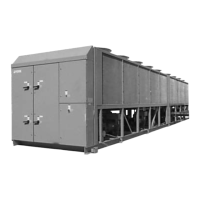
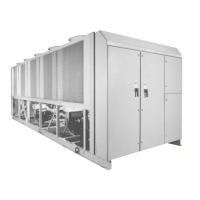
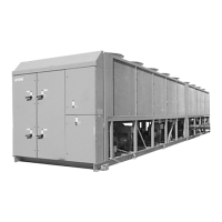
Do you have a question about the York YCAS0130 and is the answer not in the manual?
Details the warranty coverage, limitations, and conditions for YORK equipment.
Covers general safety guidelines and applicable standards for chiller operation.
Explains the procedure and components for performing an emergency shutdown.
Describes the protection mechanisms for motor current overload and undercurrent.
Details the keypad layout and functions for accessing chiller data and settings.
Explains the unit nomenclature and how to interpret the model number.
Provides information on interpreting the unit's nameplate engineering data.
Explains how to decode the product identification number for unit configuration.
Details recommendations for safe and satisfactory unit electrical connections.
Guides through the initial startup sequence and checks for the chiller.
Provides a comprehensive checklist for unit startup procedures and checks.
Details the steps to initiate the chiller's startup sequence.
Explains the automatic operation, load adjustment, and cycling of the chiller.
Describes the procedures for safely shutting down the chiller unit.
Provides detailed electrical specifications, including power supply and component data.
Illustrates electrical wiring configurations for various connection types.
Shows wiring diagrams specific to across-the-line motor starting configurations.
Provides a schematic of the chiller's electrical control circuit logic.
Overview of the control panel interface for programming and data access.
Explains keys for accessing and displaying system status and information.
Details keys used for programming setpoints, schedules, and unit parameters.
Describes the function, components, and backup battery of the microprocessor board.
Explains the motor protection features, including current and temperature monitoring.
Explains the operation of the Electronic Expansion Valve (EEV) and its controller.
Describes how condenser fans are controlled based on pressure and ambient conditions.
Outlines procedures for accessing and modifying unit setup values in service mode.
Lists common status messages indicating unit operational state.
Explains various unit warnings requiring operator attention or intervention.
Lists fault messages indicating safety thresholds have been exceeded, causing shutdown.
Explains the safety shutdown for low ambient temperature conditions.
Describes the safety shutdown for excessive compressor motor current.
Details how to view programmed options via DIP switch settings on the microprocessor board.
Explains how the chiller controls leaving chilled liquid temperature via setpoints.
Details how to program safety cutouts, unload points, and timers.
Helps diagnose and resolve low motor current or motor protection faults.


 Loading...