JOHNSON CONTROLS
35
FORM 160.69-O2
ISSUE DATE: 9/30/2020
4
SECTION 4 – OPERATIONAL MAINTENANCE
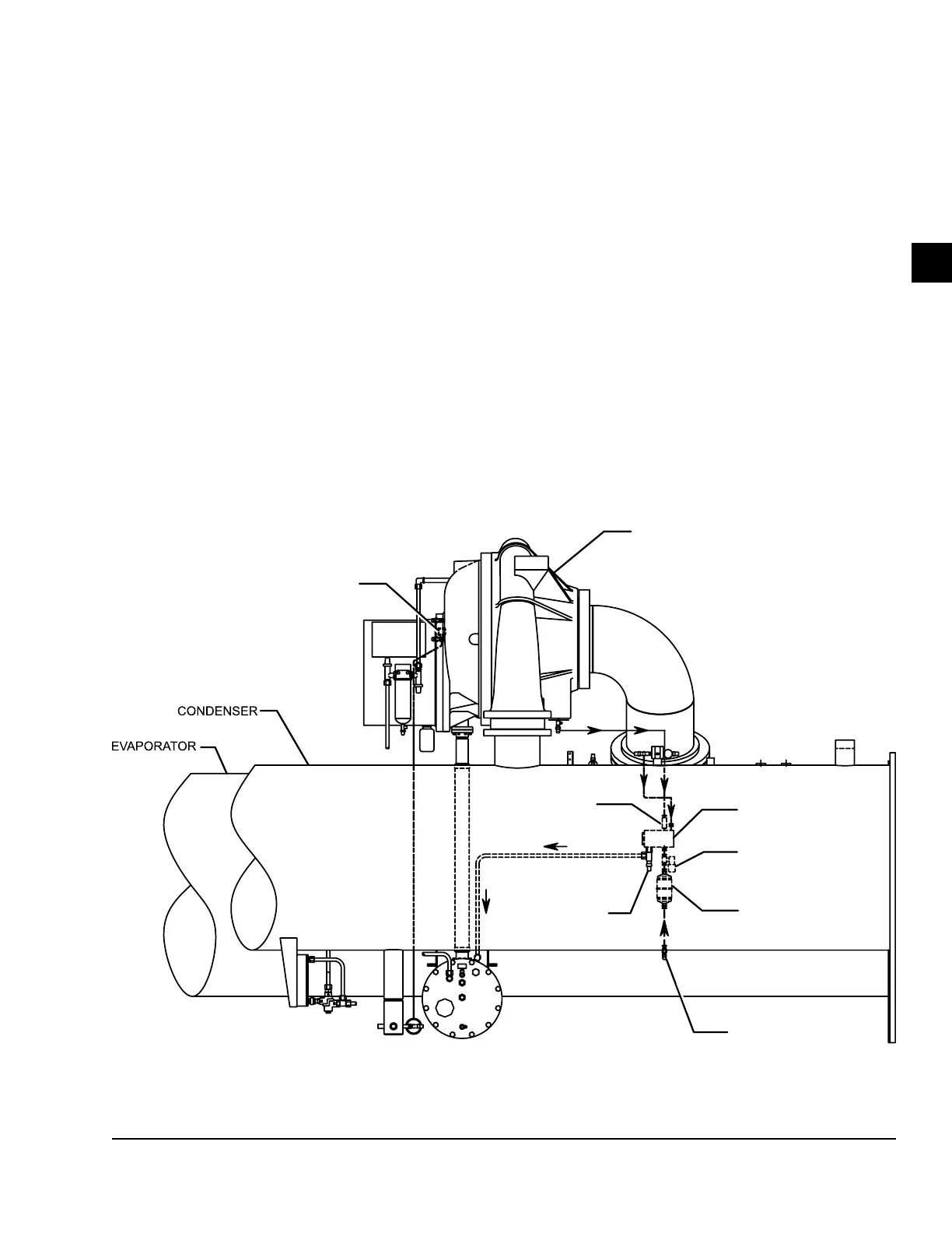
OIL RETURN SYSTEM
The oil return system continuously maintains the prop-
er oil level in the compressor oil sump.
High pressure condenser gas flows continuously
through the eductor inducing the low pressure, oil rich
liquid to flow from the evaporator, through the dehy-
drator to the compressor sump.
CHANGING THE DEHYDRATOR
To change the dehydrator, use the following procedure:
1. Shut the stop valves on the condenser gas line, oil
return line to rotor support and inlet end of the
dehydrator.
2. Remove the dehydrator. Refer to Figure 7 on page
35.
3. Assemble the new lter-drier.
4. Open condenser stop valve and check dehydrator
connections for refrigerant leaks.
5. Open all the dehydrator stop valves to allow the
liquid refrigerant to ow through the dehydrator
and condenser-gas through the eductor.
OIL EDUCTOR BLOCK
SOLENOID VALVE
SOLENOID VALVE
DEHYDRATOR
STOP VALVE
STOP VALVE
CHECK VALVE
FIGURE 7 - OIL RETURN SYSTEM
LD08578