JOHNSON CONTROLS
7
FORM 160.69-O2
ISSUE DATE: 9/30/2020
LIST OF FIGURES
LIST OF TABLES
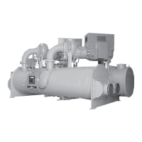
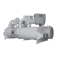
FIGURE 1 - Model YD Chiller ...................................................................................................................................9
FIGURE 2 - Chiller Operation Flow Chart ............................................................................................................... 15
FIGURE 3 - Oil Level Indicator ..............................................................................................................................23
FIGURE 4 - Liquid Chiller Log Sheets ....................................................................................................................25
FIGURE 5 - System Components ...........................................................................................................................30
FIGURE 6 - Schematic Drawing – (YD) Compressor Lubrication System .............................................................31
FIGURE 7 - Oil Return System ...............................................................................................................................35
FIGURE 8 - Charging Oil Reservoir With Oil ..........................................................................................................36
FIGURE 9 - Evacuation Of Chiller ..........................................................................................................................39
FIGURE 10 - Saturation Curve ...............................................................................................................................41
FIGURE 11 - Megging Motor Windings ..................................................................................................................43
FIGURE 12 - Motor Starter Temperature And Insulation Resistances .................................................................... 44
TABLE 1 - Operation Analysis Chart ......................................................................................................................37
TABLE 2 - System Pressures .................................................................................................................................40
TABLE 3 - Refrigerant Charge ...............................................................................................................................42
TABLE 4 - Bearing Lubrication ...............................................................................................................................49
TABLE 5 - SI Metric Conversion .............................................................................................................................51