EasyManua.ls Logo

York YGWH 115 User Manual

York YGWH 115
60 pages
To Next Page IconTo Next Page
Page #1 background imageLoading...
Page #1 background image
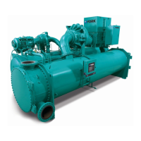
YGWH WATER COOLED SCREW CHILLERS
STYLE A
Cooling Capacities: 416 kW to 1328 kW (118 to 378 TR)
YGWH WATER COOLED
SCREW CHILLERS
Installation, Commissioning, Operation & Maintenance
FORM NO.: 6S6I-B01C-EOMA-EN(0318)
TO BE COMPLETED WHEN PICTURE IS AVAILABLE

Table of Contents

Questions and Answers:

York YGWH 115 Specifications

General IconGeneral
BrandYork
ModelYGWH 115
CategoryChiller
LanguageEnglish

Summary

General Chiller Information and Safety

Warranty

Details warranty terms, limitations, and void conditions.

Safety Standards and Responsibilities

Lists safety standards YGWH units conform to, including ISO 9001 and responsibilities.

About this manual

About this manual

Explains hazard symbols and the manual's guidance on safe practices.

Misuse of Equipment

Details prohibited uses, structural support, mechanical strength, access, pressure, and electrical safety.

Refrigerants and Oils

Refrigerants and Oils

Information on refrigerants and oils, including safety precautions for handling.

Emergency Shutdown

Describes the function and operation of the emergency stop button for safety.

Safety Labels

Explains the meaning of various safety labels affixed to the unit for hazard identification.

Material Safety Data

Refrigerant Data

Safety data for R134a refrigerant, including handling, disposal, and fire information.

Refrigerant Oil Data

Safety data for YORK 'L' Oil, including handling, disposal, and fire information.

Thermal & Acoustic Materials Data

Data on thermal and acoustic materials, including hazard and first aid.

Specification

Unit Overview and Standards

Unit assembly, testing, standards compliance, and control systems overview.

Compressor and Capacity Control

Details compressor features, bearings, motor cooling, and capacity control methods.

Motor Starting

Explains the Star/Delta starter used for compressor motor starting.

Specification Details

Oil Separator and Refrigerant Circuit

Explains oil separator, oil heater, and refrigerant circuit components and functions.

Condenser and Evaporator

Describes condenser and evaporator features, standards, materials, and connections.

Control System and Panel

Details the microprocessor control system, panel contents, and communication interfaces.

Accessories and Options

Lists available accessories like flow switches and isolators for enhanced functionality.

Unit Identification and Flow

Nomenclature

Explains the model number coding system for YGWH units.

Component Location Diagram

Illustrates the physical locations of major unit components with numbered labels.

Refrigerant Flow Diagram

Refrigerant Flow Diagram

Illustrates the path of refrigerant through the system components using a schematic.

Rigging, Lifting, Handling and Storage

Rigging and Lifting Safety

Emphasizes professional riggers, planning, and safety precautions for lifting.

Weights and Weight Distribution

Provides shipping/operating weights and point load distribution data for models.

Handling and Storage Procedures

Delivery and Storage Guidelines

Guidelines for unit delivery, storage, and precautions to maintain quality.

Inspection Procedures

Procedures for inspecting the unit upon arrival and at the job site for damage.

Rigging Procedures

Details site suitability, lifting methods, and using spreader bars to prevent damage.

Installation

General Installation and Warranty

General installation requirements and warranty void conditions for proper setup.

Location Requirements

Specifies suitable installation locations, temperature, altitude, and clearances.

Vibration Isolator Installation

Information on optional isolators, placement, and leveling for unit stability.

Spring Isolator Installation

Installing Option Spring Isolators

Detailed steps for installing spring isolators and leveling the unit for optimal operation.

Floor Layout Diagram

YGWH Floor Layout Diagram

Diagrams showing layout for rubber and spring isolator pads for positioning.

Piping and Water Treatment

Piping Connections Recommendations

Recommendations for safe and satisfactory unit piping connections to prevent damage.

Water Treatment Guidelines

Guidelines for water quality, pH, and treatment to prevent fouling and corrosion.

System Connections and Water Quality

Water Quality Requirements

Table detailing acceptable water quality parameters for chiller operation and potential issues.

Pipework and Refrigerant Relief Piping

Pipework arrangements and safe refrigerant relief valve piping for system integrity.

Electrical Connection and Condenser Water System

Electrical connection recommendations and condenser water system control for stable operation.

Control and Wiring Strategies

Pressure Control Methods

Direct pressure, inlet temperature, and variable primary flow control methods for optimization.

Power Wiring Requirements

Guidelines for power supply voltage variation and single point wiring for safe installation.

Control Panel Inputs and Outputs

Control Panel Wiring and Outputs

Wiring details for I/O board, pump starter, and alarm outputs for system integration.

24 Vdc Inputs and Remote Control

Inputs for flow switches and remote run/stop functionality for external control.

Customer Connections

Customer Connections Diagram

Diagram and notes for connecting external components to the control center for operation.

Commissioning

Preparation and Safety Checks

Preparation, power off, inspection, valve checks, and isolation for safe commissioning.

System Component Checks

Checking control panel, power connections, earthing, oil heater, and water system integrity.

Brine Chiller and Flow Switch Checks

Low temp brine chiller checks and flow switch verification for proper operation.

Operational Setup and Startup

Control Panel Power and Settings

Confirming panel power, programmed options, settings, and time/date for unit configuration.

Startup Procedures

Setting startup/stop programming, setpoints, and first-time startup steps with oil pressure verification.

Unit Operation

Unit Operation Overview

Unit operation modes (standalone or networked) and control system functions.

OptiView™™ LT Panel Interface

Panel interface for unit control, parameter access, and fault viewing.

Startup and Running Modes

Procedures for startup, normal running, and compressor cycling for efficient operation.

Main (Home) Page Interface

Main (Home) Page Interface

Displays unit status, temperatures, pressures, and time. Includes ON/OFF control.

Panel Navigation and Access

Access Level and Navigation

Controls access levels, navigation via function/home keys, and password entry for security.

Parameter Adjustment

Parameter Modification Methods

Modifying programmable, option, digital, and binary parameters via interface.

Function Page Navigation

Function Page Navigation

Navigates between View, Configure, History, Schedule, Setting pages with access level indicators.

View Pages Data Display

View Pages Data Display

Displays component operating data, pressures, status, and runtime for monitoring.

Configure Pages for Settings

Configure Pages for Settings

Setting unit operating mode and parameters, with detailed tables for configuration.

Compressor Configuration

Compressor Configuration Parameters

Lists and describes parameters for compressor configuration and monitoring.

History Page

History Page for Faults

Accesses historical data on faults, safeties, and events for analysis.

Data Monitoring and Trends

Parameter Check and Trend Monitoring

Lists parameters for checking and creating trends for diagnosis and performance monitoring.

Parameter Trend Creation

Parameter Trend Creation

Steps to add and configure parameter trends, including sample interval for data logging.

Schedule Page

Schedule Page for Timing

Setting schedules, holidays, and alternate days for unit operation control based on time.

Setting Pages

Setting Pages for Service

Adjusting display, system date/time, and viewing version information for service.

Maintenance

General Maintenance Requirements

Emphasizes continuous operation with regular maintenance schedules.

Daily Maintenance Checks

Daily checks by operator/customer, emphasizing limitations and reporting issues.

Refrigerant Handling and Leak Checking

Procedures for periodic leak checking and refrigerant charge verification.

Refrigerant Charge Level Determination

Methods to verify correct refrigerant charge using approach and superheat.

Component Maintenance

Compressor Oil Management

Oil analysis, changing, and adding oil procedures for compressor longevity.

Condenser, Evaporator, and Water Treatment

Maintaining shells, and chemical water treatment for corrosion prevention and efficiency.

Tube Cleaning Procedures

Tube Cleaning Procedures

Procedures for chemical and mechanical cleaning of condenser and evaporator tubes for optimal heat transfer.

Evaporator and Scheduled Maintenance

Evaporator Tube Maintenance

Evaporator tube care, freezing prevention, and performance diagnosis for potential issues.

Working Conditions and Scheduled Maintenance

Confirming operating limits and outlining scheduled service intervals (minor/major).

Trouble Shooting

Competent Persons Trouble Shooting Guide

Table of common problems, causes, and actions for diagnosis and resolution.

Troubleshooting Specific Issues

Motor and Oil Troubleshooting

Troubleshooting high motor temperature, current limiting, and oil pressure issues.

Noise, Vibration, and Fault Overview

Addressing noise/vibration and introducing safety faults, stops, and warnings.

Specific Safety Faults

Details specific safety faults like High Pressure, Low Level, Motor Protection.

Safety Faults - Sensors and Pressure

Safety Faults - Sensors and Pressure

Continues listing safety faults related to sensors (temp, pressure) and system pressures.

Safety Faults - Compressor and Motor Temps

Safety Faults - Compressor and Motor Temps

Continues listing safety faults for compressor, motor temperatures, and related sensors.

Safety Faults and Cycling Stops

Safety Faults - Other & Cycling Stops

Details faults for emergency stop, freeze protection, communication, and cycling stops.

Warning Codes

Warning Codes

Lists warnings for low/high pressure, freeze protection, and system status conditions.

Temperature and Current Warnings

Warning Codes - Temperature and Current

Lists warnings for discharge superheat, motor temperatures, and current limits.

Sensor Calibration

Sensor Calibration Charts

Provides calibration data for temperature sensors to ensure accuracy.

Technical Data

Operational Limits Tables

Tables detailing operational limits for various YGWH models (temp, pressure, flow).

Pressure Drop Information

Information on expected waterside pressure drop and calculation methods.

Physical and Electrical Data

Physical Data Tables

Tables showing refrigerant/oil charge, compressor type, dimensions, and weights for models.

Electrical Connections Recommendations

Recommended input cable sizes for different models based on electrical requirements.

Model Dimensions

YGWH Model Dimensions (115-225)

Dimensional drawings and data for specific YGWH models (115 to 225).

Larger Model Dimensions

YGWH Model Dimensions (260-375)

Dimensional drawings and data for larger YGWH models (260 to 375).

Spare Parts Information

Obtaining Spare Parts and Oils

Information on obtaining spares and recommended compressor oils for maintenance.

Decommissioning, Dismantling and Disposal

General Unit Removal Procedures

Procedures for isolating electrical supply, disconnecting cables, and removing units safely.

Safe Handling of Refrigerant, Oil, and Glycol

Safe handling and disposal of refrigerant, oil, and glycol solutions according to regulations.

Related product manuals