youngmangroup.com
Step 4: Deploying the Platform Stabilisers
14
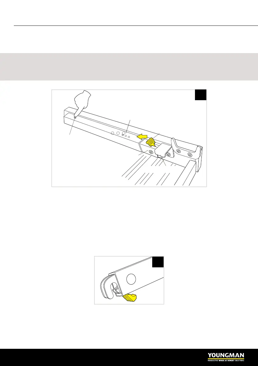
The platform is equipped with four platform stabilisers (braces) which are stowed
on the underside of the platform, see Figure 4.1.
Warning
The platform stabilisers MUST be deployed when the platform working height is at
or greater than 1.50 metres.
Press the release button at the far end of the stabiliser and pull back on the yellow
lever to release it from the stowage bracket. The stabilisers are hinged centrally on
the platform and when deployed anchor to brackets on the inner face of RUNGS 5,
6 & 7.
The stabilisers are telescopic in construction and adjustable to three different
lengths to suit the three platform heights that require platform stabilisers to be used.
The free end has a spring self-locking slot, see Figure 4.2.
There is a spring-loaded ball locking mechanism which holds the stabiliser at any
of the three preset extensions. The stabiliser has a viewing window in its side that
lets you easily adjust it to the correct length using a colour coded system. The
brackets are also coloured, see Figure 4.3.
PLATFORM
STABILISER
STOWED
PLATFORM STABILISER
STOWAGE BRACKET
PULL LEVER TO
RELEASE STABILISER
PLATFORM
LOCKING BALL
MECHANISM
PUSH DOWN TO
RELEASE THE
LOCK
EXTENSION POSITIONS
4.1
4.2
 Loading...