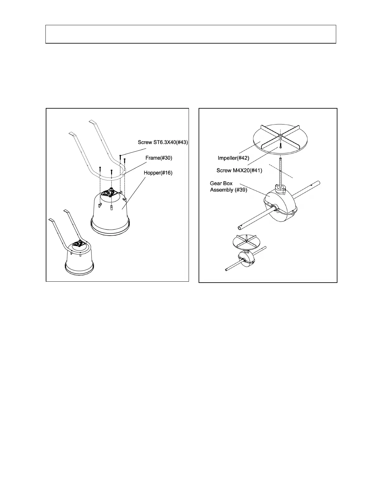
1. Turn Hopper (#16) upside down and attach Frame (#30) using four screws ST6.3 x 40
(#43).
2. Slide the Impeller (#42) onto the spindle of the Gear Box Assembly (#39).
3. Align the Impeller (#42) with the hole closest to the Gear Box (#39) in the spindle. Then
insert Screw M4 x20 (#41) through the hole and fasten tight.
1. Insert the spindle through the center hole in the Hopper (#16) base.
2. Slide the Wheel Assembly Frames (#20) over the ends of each axel with the bent ends
facing inward towards each other.
4. Secure the other end of each Wheel Assembly Frame (#20) to the outside of the Hopper
Frame Assembly (#30).
5. Align the middle hole of each Wheel Assembly Frame (#20) with the lowest hole on each
Hopper Frame Assembly (#30).
6. Insert M6 x 60 bolt (#32) and tighten with Lock Nut M6 (#24). NOTE: The nuts and bolts
should not be fully tightened until the Frame Braces (#31) are attached.
7. Attach one end of each Frame Brace (#31) to the outside of the Hopper Frame Assembly
(#30) using bolt M6 x 35 (#33) and M6 lock nut (#24). Ensure the other end is bending in
towards the hopper.
8. Attach the other end of each Frame Brace (#31) to the inside of the Wheel Assembly
Frame (#20) using bolt M6 x 35 (#33) and M6 lock nut (#24).
1
2