EasyManuals Logo

Yudian AI Series Operating Instructions

Yudian AI Series
9 pages
To Next Page IconTo Next Page
To Previous Page IconTo Previous Page
Page #3 background imageLoading...
Page #3 background image
3
Wiring diagram of AI-70482 multi-channel
temperature controller
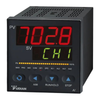
Wiring diagram and explanation of indicating lights of D5 panel
MODE: Status of communication and alarm
OP1~OP4: Output of channel 1~4.
Terminal 1~2: Power 100~240VAC or 24VAC/DC
Terminal 9~12: Positive poles of 4 thermocouple inputs
Terminal 15~16: Negative poles of 4 thermocouple inputs in common.
Terminal 5~8: Positive poles of 4 SSR voltage outputs
Terminal 3~4: Negative poles of 4 SSR voltage outputs in common. The
specification of SSR outputs is 12~16VDC/20mA with short-circuit
protection.
Terminal 13~14: RS485 communication.
No alarm output is available in this D5 panel.
This wiring diagram is valid for panel size code A, C, E, E5
or etc.
For instruments with dimension B and F, the diagram is
clock-wisely rotated by 90°. The terminal numbers keep
unchanged.

Other manuals for Yudian AI Series

Questions and Answers:

Question and Answer IconNeed help?

Do you have a question about the Yudian AI Series and is the answer not in the manual?

Yudian AI Series Specifications

General IconGeneral
Control ModeOn/Off
Input TypeThermocouple (K, S, T, E, J, B, N), RTD (Pt100, Cu50), Linear Current (4-20mA), Linear Voltage (0-5V, 1-5V)
Output TypeRelay, SSR, Linear Current (4-20mA)
Power SupplyAC 90-260V, 50/60Hz or DC 24V
CommunicationRS485 Modbus RTU
Accuracy±0.2%FS
Operating Temperature0-50°C
Storage Temperature-20-60°C
Humidity85% RH (non-condensing)
ProtectionIP65 (Front Panel)

Related product manuals