D7 multi-channel temperature controller
Wiring diagram
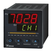
Power Base Terminals
Terminal 1~2: Power 100~240VAC or 24VAC/DC
Terminal 4~5: RS485 communication.
Instrument Terminals
Terminal 5~8: Positive poles of 4 SSR voltage
outputs
Terminal 9~10: Positive poles of AL1 and AL2
SSR alarm outputs.
Terminal 11~12: Negative poles of AL1 and AL2
SSR alarm outputs.
The specification of SSR outputs is 12~16VDC/20mA
with short-circuit protection.
Terminal 13,14,17,18: Positive poles of 4
thermocouple inputs
Terminal 15,16,19,20: Negative poles of 4
thermocouple inputs
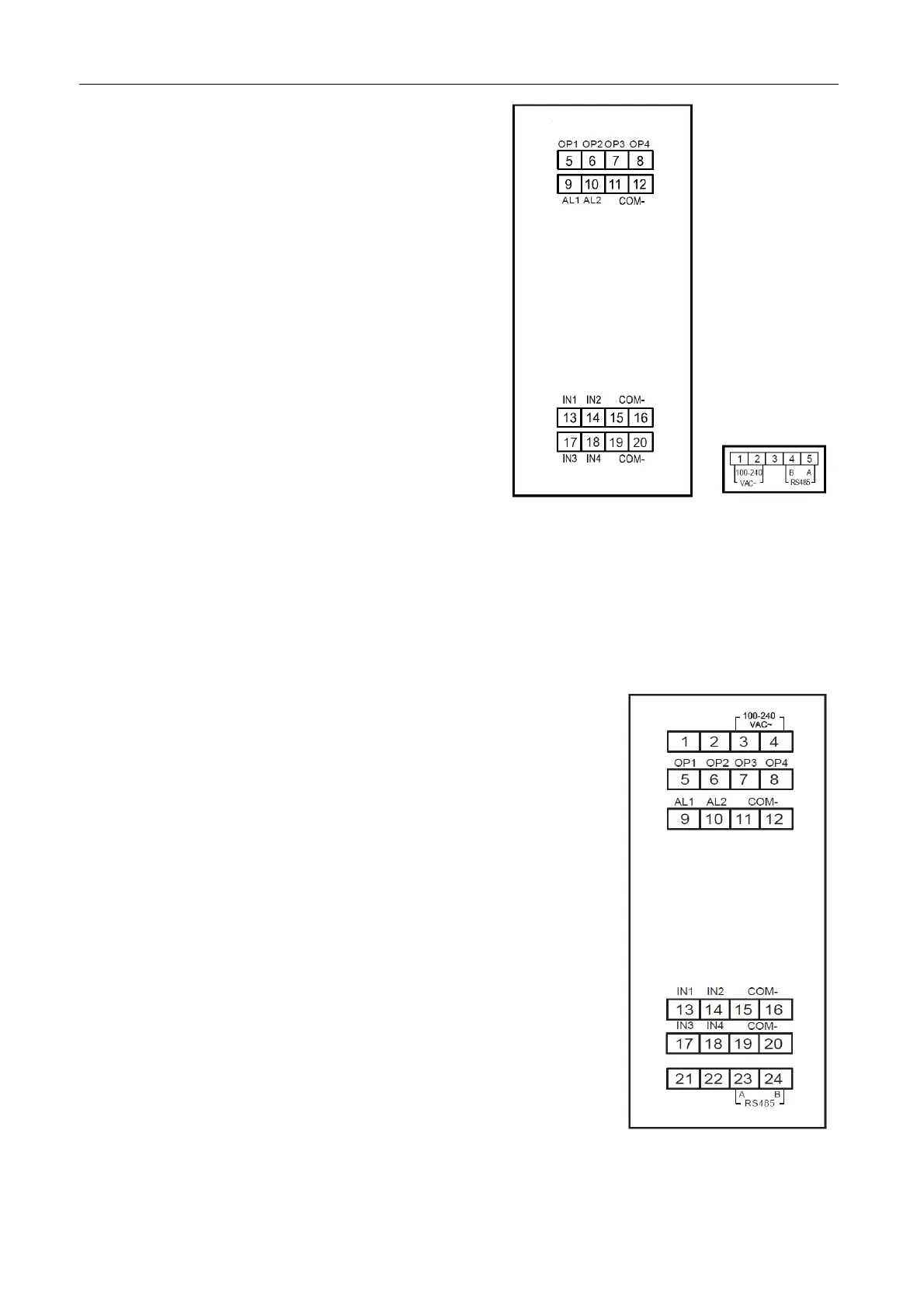
E7 multi-channel temperature controller
Wiring diagram
Terminal 3~4: Power 100~240VAC or 24VAC/DC
Terminal 5~8: Positive poles of 4 SSR voltage outputs
Terminal 9~10: Positive poles of AL1 and AL2 SSR alarm outputs.
Terminal 11~12: Negative poles of AL1 and AL2 SSR alarm
outputs.
The specification of SSR outputs is 12~16VDC/20mA with
short-circuit protection.
Terminal 13,14,17,18: Positive poles of 4 thermocouple inputs
Terminal 15,16,19,20: Negative poles of 4 thermocouple inputs
Terminal 23~24: RS485 communication.
 Loading...