Do you have a question about the Zamp Solar SCC1011 and is the answer not in the manual?
Highlights the use of Pulse Width Modulated (PWM) technology for high efficiency operation in the solar controller.
Lists supported battery types including LiFePO4, LTO, LI-95, Gel, AGM, and Conventional lead-acid.
Details built-in regulators to prevent overcharging and features for deeply drained batteries.
Explains the permanent connection capability for keeping batteries fully charged via a floating process.
Provides critical warnings for indoor use, avoiding disassembly, and handling batteries safely.
Advises on eye protection, preventing short circuits, and covering panels during installation.
Describes the simple surface mounting method using plastic spacers and self-tapping screws.
Details the flush mounting procedure, including required panel cut-out dimensions.
Strongly recommends placing 50A inline fuses on positive wires for both Solar and Battery circuits.
Provides a chart to determine correct wire sizes (AWG) for optimal solar regulator performance.
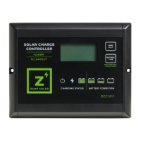
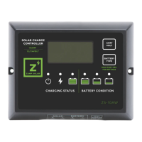
Explains the LCD's role in displaying battery voltage, charging current, capacity, and battery types.
Instructs users to select the correct battery type via the LCD for optimal charging performance.
Details the 5-stage charging algorithm: Soft Charge, Bulk Charge, Absorption, Equalization, and Float.
Describes how the six LEDs indicate charging status and battery condition.
Details specific LED patterns for Soft, Bulk, Absorption, Equalization, and Float charging stages.
Covers abnormal modes related to solar panel weakness, reverse connection, and over voltage.
Details abnormal modes for battery disconnection, reverse connection, over voltage, and temperature.
Explains the abnormal mode for the controller experiencing over-temperature protection.
Describes the optional sensor for optimizing charging and providing temperature-based protection.
Explains the optional remote display meter for monitoring the controller's status remotely.
Lists key electrical specifications including input voltage, current, and controller operating voltage.
Details voltage and current settings for various charging stages like bulk, absorption, and float.
Outlines protection mechanisms such as reverse polarity, over-temperature, and transient voltage.
Specifies operating and storage temperature ranges, and humidity limits for the controller.
| Category | Solar Charge Controller |
|---|---|
| Model | SCC1011 |
| Rated Current | 10A |
| Battery Voltage Compatibility | 12V |
| Max Solar Input (Amps) | 10A |
| Maximum Input Voltage | 25V |
| Charging Technology | PWM |
| Display | LED indicators |
| System Voltage | 12V |
| Max Solar Input (Volts) | 25V |
| Charging Algorithm | 3-Stage (Bulk, Absorption, Float) |
| Protection Features | Reverse Polarity, Overload, Short Circuit |
| Operating Temperature Range | -20°C to +60°C |
| Weight | 0.5 lbs |