4) LOGIC FAILURE #2
Fault in the hardware section of the logic board which manages the phase' s
voltage feedback. Replace the logic board.
5) LOGIC FAILURE #3
Fault in the hardware section of the logic board which manages the hardware
current protection. Replace the logic board.
6) INCORRECT START
This alarm signals an incorrect starting sequence. Possible causes:
A) running microswitch failure;
B) error in sequence made by the operator;
C) incorrect wiring;
D) if the default persists, replace the logic.
7) ENCODER ERROR
Two consecutive readings of the encoder speed are too much different in
between: because of the inertia of the system it is not possible the encoder
changes its speed a lot in a short period. Probably an encoder failure has
occurred (e.g. one or two channels of the encoder are corrupted or
disconnected). Check both the electric and the mechanical encoder
functionality. Also the electromagnetic noise on the sensor bearing can be a
cause for the alarm.
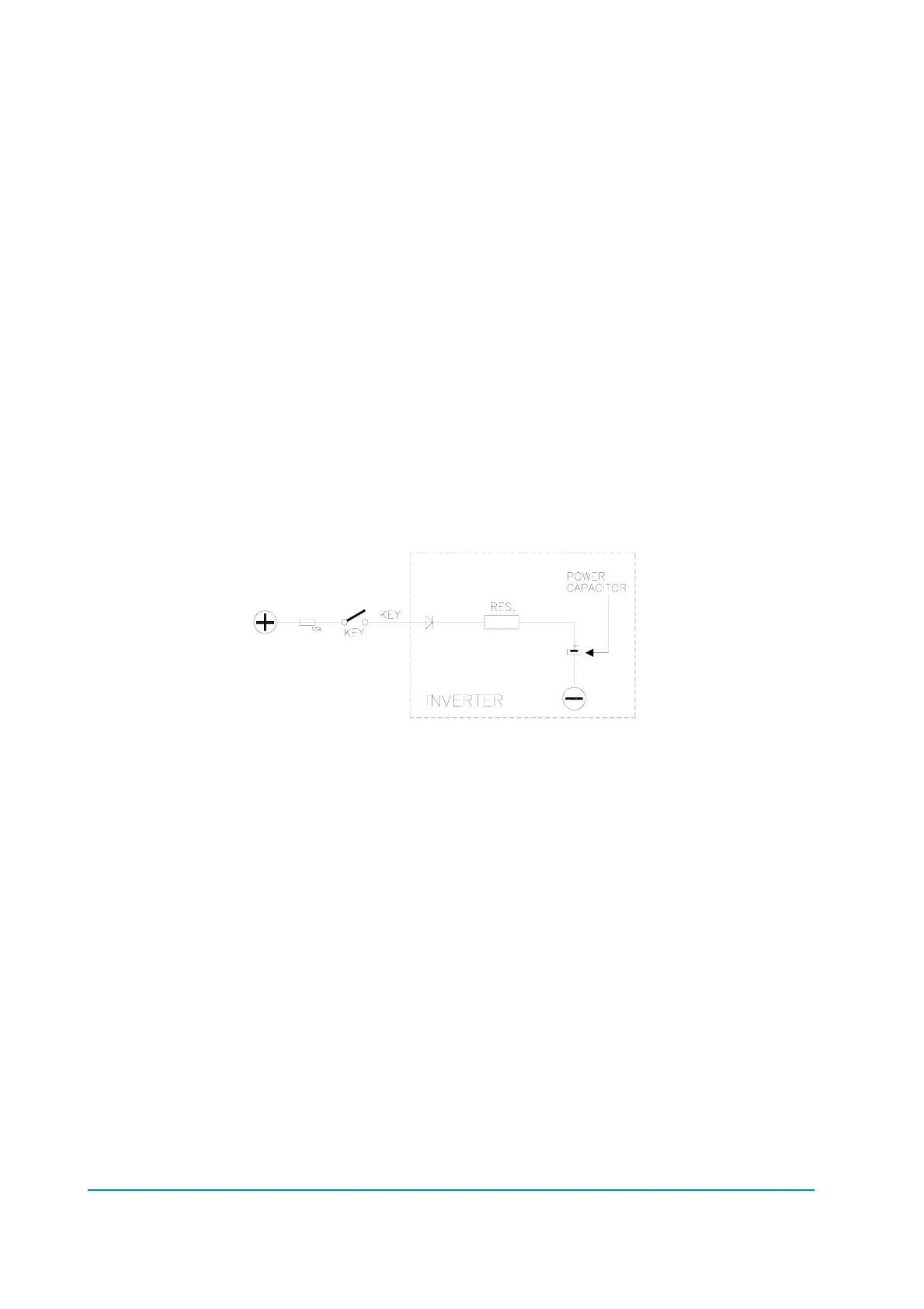
8) CAPACITOR CHARGE
Follows the charging capacitor system:
When the key is switched ON, the inverter tries to charge the capacitors
through a power resistance and check if the capacitors are charged within a
timeout. If this is not true: an alarm is signalled; the main contactor is not
closed.
Possible reasons:
A) check if the charging resistance is opened.
B) The charging circuit has a failure.
C) There is a problem on the power modules.
9) VMN LOW, VMN HIGH
The test is carried out during initial diagnosis and in standby.
Possible causes:
A) problem with the motor connections or the motor power circuit; check if
the 3 phases are correctly connected; check if there's a dispersion of the
motor towards ground;
B) controller failure, replace it.
10) PEDAL WIRE KO
This alarm is signalled if a fault is detected in the accelerator wiring (NPOT or
PPOT cable is interrupted).
11) VACC NOT OK
The test is made in standby. This alarm indicates that the accelerator voltage
is 1V greater than the minimum value programmed by the PROGRAM VACC
function.
Page - 60/64 ADEZP0AE - AC-2 INVERTER - User Manual