H2B USER'S MANUAL - 550145G Page 7/60
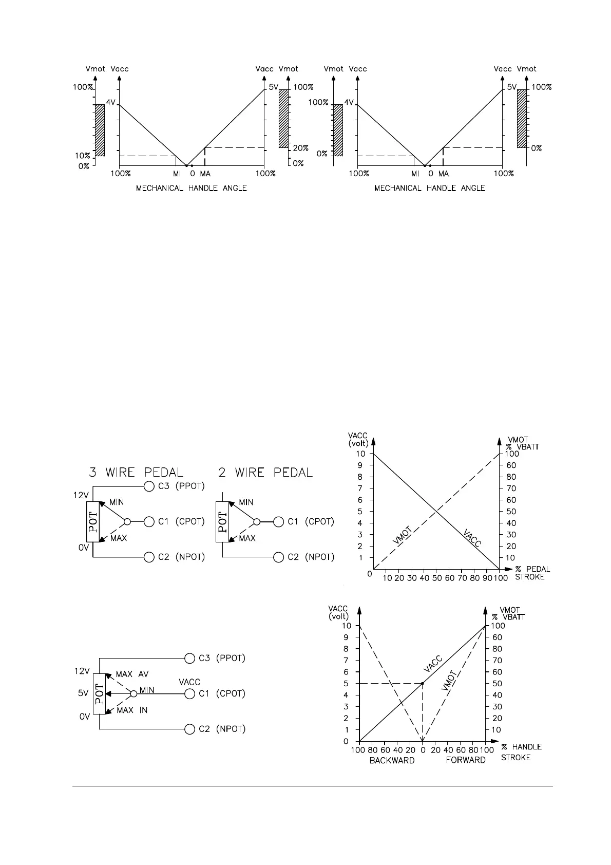
fig. 8a fig. 8b
The two graphs show the output voltage from an uncalibrated potentiometer with respect to
the mechanical “zero” of the knob of one handle (MI and MA indicate the point at which the
speed microswitches close, 0 is the mechanical zero of the handle rotation). The first graph
(Fig. 8a) shows the correspondence of the motor voltage without having made the acquisi-
tion, while the second graph (Fig. 8b) shows the same correspondence after signal acqui-
sition by the potentiometer. The acquisition procedure is invalidated by the machine if the
difference between the maximum value and the minimum value is less than 2V.
This acquisition procedure makes it possible:
- to use “reversed” potentiometric signals, i.e. those which are carried from a high initial
value to a low final value.
- to use a normal potentiometer instead of one with central zero.
For the correct functioning of signal acquisition, it is absolutely necessary that the running
microswitches be activated by the same shaft that moves the potentiometer.
Application examples.
- Signal overturn.
VACC = accelerator signal voltage to pin C1.
VMOT = percentage of batt. voltage on the motor.
- Central zero signal.