Page 2-6 105SL Maintenance Manual 32056L Rev. 2 12/4/01
SECTION 2 OPERATION OVERVIEW
For all RS-232 data and control input and output signals, the Zebra 105SL follows both the
Electronic Industries Association’s (EIA) RS-232 and the Consultative Committee for
International Telegraph and Telephone (CCITT) V.24 specifications.
'DWD&DEOH5HTXLUHPHQWV
Data cables must be fully shielded and fitted with metal or metallized connector shells.
Shielded cables and connectors are required to prevent radiation and reception of electrical
noise.
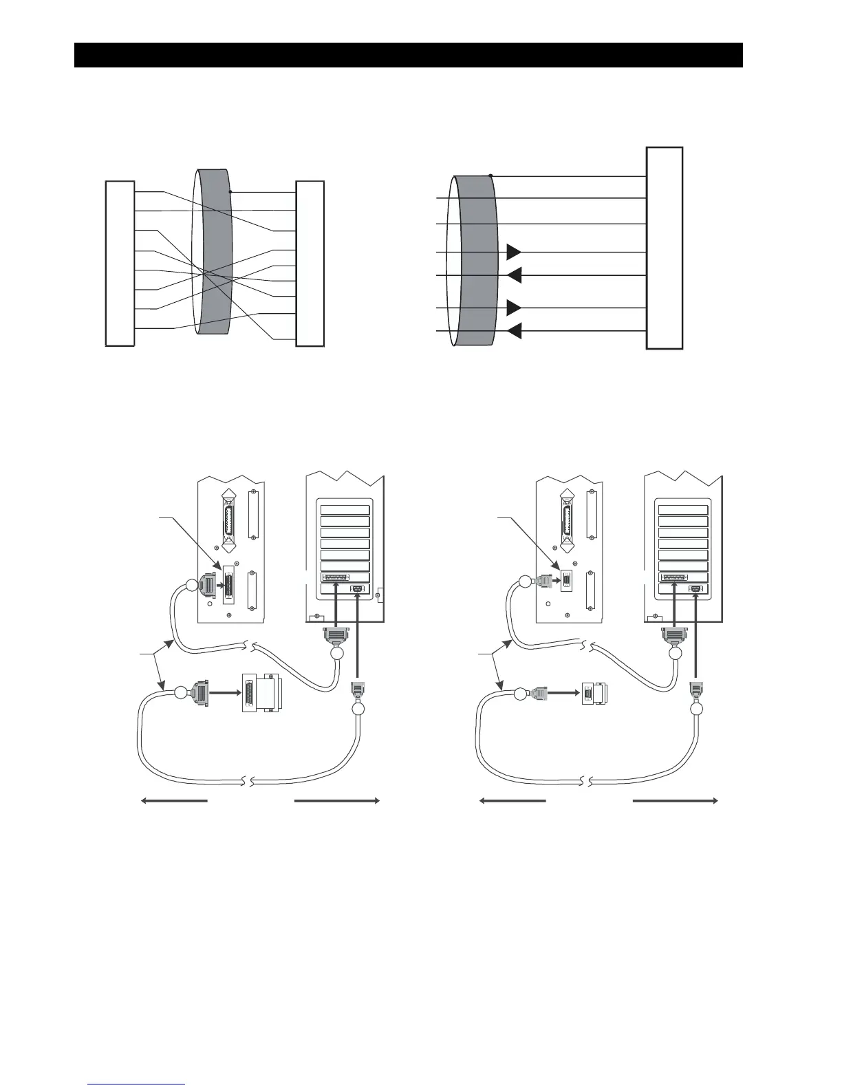
Figure 2-4. Supplied Serial Interface Adapters
Figure 2-5. Serial Data Connection
Female DB25 Connector on
RS-422/RS-485 Adapter
Data input B(-)
Data input A(+)
Data output B(-)
Data output A(+)
Frame ground
Signal ground ref.
+5VDC 725 mA source
1
9
11
13
14
16
19
NOTE: Pins 2-8, 10, 12, 15, 17-18, 20-25 are unused and unterminated.
Male DB-9 Adapter
Connector
(plugs into printer)
Female DB-25 Adapter
Connector
(plugs into cable)
NOTE: Pin 1 of DB9 connector is unused and unterminated.
FG
TXD
RXD
RTS
DSR
SG
DTR
RXD
TXD
DTR
SG
DSR
RTS
CTS
+5VDC
SIGNAL
2
3
4
5
6
7
8
9
1
2
3
4
6
7
9
20
+5VDC
SIGNAL
5
CTS
DB-9 to DB-25 Adapter
RS-422/RS-485 Adapter
25
9
25
25
Null modem adapter
(if using a standard
modem cable)
Null
Modem
Cable
DB-25
Serial
Interface
Connector
Male
50 maximum
Female
ComputerPrinter
Male
25
9
9
9
Null modem adapter
(if using a standard
modem cable)
Null
Modem
Cable
DB-9
Serial
Interface
Connector
Male
50 maximum
Female
ComputerPrinter
Male
Printers with a DB-25 Serial Connector
Printers with a DB-9 Serial Connector