32056L Rev. 2 12/4/01 105SL Maintenance Manual Page 2-9
OPERATION OVERVIEW SECTION 2
NOTE: Pin 9 is also available as a +5 VDC power source at 750 mA. To enable this
capability, a jumper needs to be installed between pins 2 and 3 at JP1 on
the Main Logic Board.
The pin outs and signal descriptions for the RS-422/RS-485 adapter are as follows:
Pin 1—FG (Frame ground) for cable shield.
Pin 9—+5VDC source (1 Amp maximum)
Pin 11—SGR (Signal ground reference) RS-422/RS-485
Pin 13—Data input B(–) RS-422/RS-485
Pin 14—Data output B(–) RS-422/RS-485
Pin 16—Data input A(+) RS-422/RS-485
Pin 19—Data output A(+) RS-422/RS-485
Pins 2–8, 10, 12, 15, 17-18 and 20-25 are not used and are not terminated.
6HULDO&RPPXQLFDWLRQ6LJQDO/HYHOV
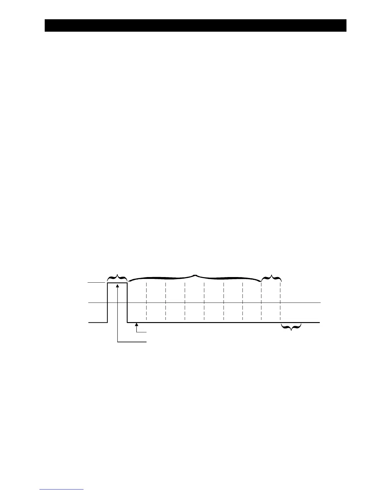
Refer to Figure 2-8. RS-232 data signals are defined as either “Mark” or “Space”, while control
signals are ON (Active-Positive Voltage) or OFF (Inactive-Negative Voltage). Although the
permitted voltage levels can range from ±3 VDC to ±25 VDC, the levels for the 105SL printer
are as follows:
RS-232 Transmit and Receive Data
Mark or OFF = –7 to –10 VDC
Space or ON = +7 to +10 VDC
Refer to Figure 2-9. RS-422 and RS-485 data signals are also either Mark or Space. The
voltage levels are +5 VDC and 0 VDC when monitored from a specified reference point. The
levels for the 105SL printer when referenced to signal ground are:
RS-422 and RS-485 Transmit and Receive Data
Mark Output/Input A = +5V and Output/Input B = 0V
Space Output/Input A = 0V and Output/Input B = +5V
Figure 2-8. RS-232 Signaling
+Space
0 Vdc
- Mark