Do you have a question about the Zeck Audio A602 and is the answer not in the manual?
Crucial warnings regarding personal injury, component damage, and proper service procedures.
Precautions against static discharge to protect sensitive electronic components.
Identification of safety-critical parts marked with '!' for correct replacement.
Visual guide to the pin configurations of various electronic components used in the unit.
Detailed steps for setting the amplifier's idle current to the specified 20mA.
| Frequency Response | 20 Hz - 20 kHz |
|---|---|
| S/N Ratio | > 100 dB |
| Frequency Response Tolerance | +/- 0.5 dB |
| Signal-to-Noise Ratio | > 100dB |
| Input Impedance | 20k Ohms |
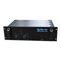
| Dimensions | 483 x 88 x 380 mm |
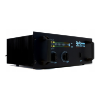
| Type | Stereo Power Amplifier |