12
Let’s begin!
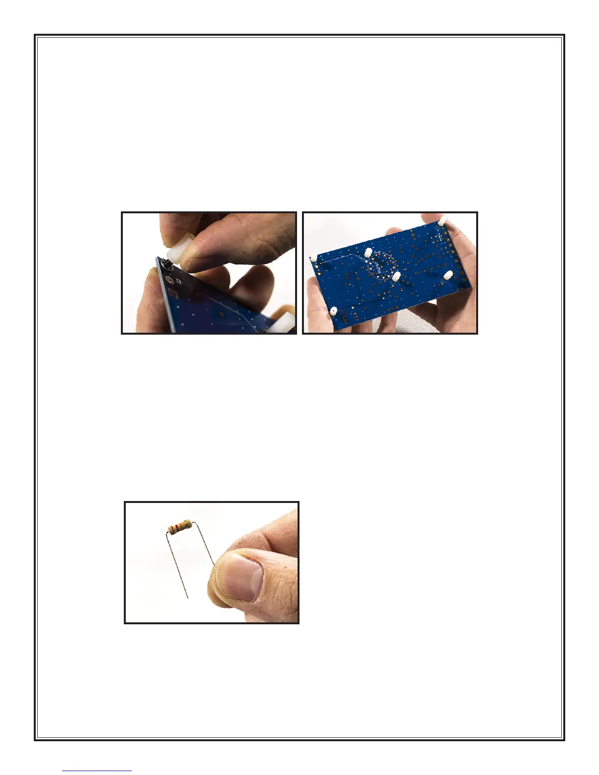
1. Standoffs (Part # SP11): Use 6 standoffs, 6 M3 screws (Part # SC38), and 6 lock washers (Part
# WA07). The plastic standoffs are installed on the solder side of the board, which means they
are screwed in from the component side. The lock washer goes between the PCB and the standoff
(not between the screw head and the PCB)
1
. Place the 6 standoffs in the locations indicated
below
2
.
2. Resistors: The value of resistors are given by a series of colored stripes on their body. There are
several tutorials on line describing how to decode these stripes, but we will identify each resistor
for you by simply naming the stripe colors, and giving you the value and the part number. Figure
2: Component Values and Locations on the next page is a handy reference. If you are color blind
or can’t see the stripes clearly, then you must use your digital multimeter to measure the resistance
of each resistor.
3. The hole spacing of most of the resistors on the circuit board allows the leads to be (gently) bent
90 degrees at the body of the resistor
3
. This allows most resistors to slip into their holes very easily.
Resistors R13 & R17 are exceptions to the normal hole spacing, so for those two components
you’ll have to estimate where to bend the leads.
1 2
3