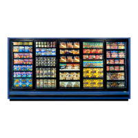
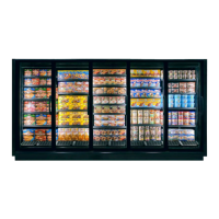
RVZC30 (and BB/T/TBB/WA), RVZP30 (and BB/T/TBB/WA), RVC24
16
0407
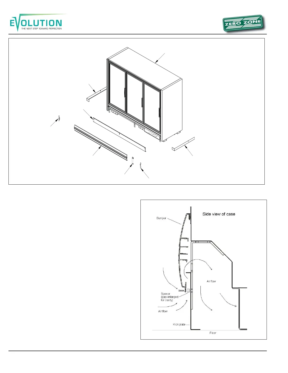
Figure 15: Bumper air flow
UNDER CASE RETURN AIR FLOW ASSEMBLY
INSTRUCTIONS
To assemble the bumper for under case return airflow, a spacer
(provided) must be inserted between the bumper and kick plate
(Figure 15). The spacer is held in place with the standard black
assembly screw used to attach the bumper. One 3/8” spacer is
required at each screw location (2 spacers on a 2-door, 3
spacers on a 3-door).
1. To ease installation, hook the bumper to the case and
position the kick plate. Then pull the bottom edge of the
bumper forward, hold the spacer in place, and then
insert the assembly screw through the bumper, spacer,
kick plate, bumper bracket and into the Tinnerman clip.
2. With the spacers in place, air will be allowed to flow
between the bumper and kick plate and then underneath
the case. The target airflow rate under the case should
be 50 cfm/door.
Figure 14: Installing bumper and kick plate
VZ CASE
END KICKPLATE
END KICKPLATE
BUMPER END
KICKPLATE
BUMPER
BUMPER SPLICE
BUMPER END