RVZC30 (and BB/T/TBB/WA), RVZP30 (and BB/T/TBB/WA), RVC24
20
0407
R 404a Frozen Food R 404a Ice Cream
RACK SYSTEMS RACK SYSTEMS
VZ and VZT 30” door VZ and VZT 30” door
Evaporator temp -7°F Evaporator temp -16°F
VZ 24” door and WA and WB VZ 24” door and WA and WB
Evaporator temp -11°F Evaporator temp -18°F
CONDENSING UNIT CONDENSING UNIT
VZ and VZT 30” door VZ and VZT 30” door
Condensing unit cut in 35 psig Condensing unit cut in 27psig
Condensing unit cut out 24 psig Condensing unit cut out 16 psig
VZ 24” door and WA and WB VZ 24” door and WA and W
Condensing unit cut in 33 psig Condensing unit cut in 26 psig
Condensing unit cut out 21 psig Condensing unit cut out 15 psig
RETURN & DISCHARGE RETURN & DISCHARGE
AIR TEMPERATURE AIR TEMPERATURE
Return air temp cut in +6°F Return air temp cut in -3°F
Return air temp cut out 0°F Return air temp cut out -9°F
Discharge air temp cut in +3°F Discharge air temp cut in -3°F
Discharge air temp cut out -3°F Discharge air temp cut out -12°F
Note: These set points may require optimization for your
applications to prevent short-cycling or delayed cycling.
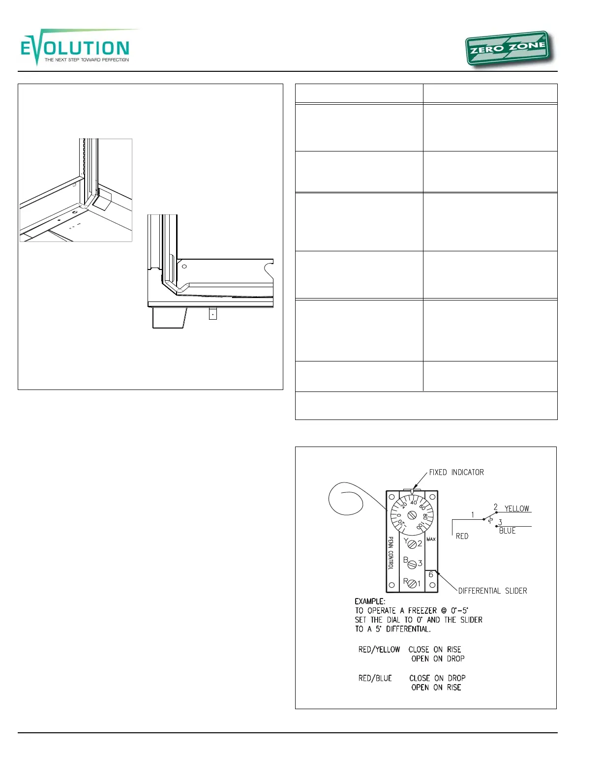
Figure 18: 45° elbow suction line
Temperature Control Adjustment
When factory installed, the temperature control is located to-
ward the right end of the case behind the black kick plate. The
sensing bulb is located under the coil cover on the back side of
the fan shroud. It can be wired in series with the low-pressure
(L.P.) control. It can also be used in a pump down system by
wiring it in series with the liquid solenoid valve. A thermostat is
shown in Figure 20.
Discharge air temperature probes for electronic case control-
lers may be installed in many different customer specified lo-
cations including, but not limited to, honeycomb, ceiling pocket
cover, rear wall, and return air.
Leak Check-Evacuation-Charging
After all of the refrigeration piping and system components
have been assembled, the entire system must be pressurized
and checked for leaks.
When the system is leak free, evacuate with a deep vacuum
pump. Triple evacuation to a minimum of 500 microns and ni-
trogen sweep is recommended. After the system has been thor-
oughly evacuated of all moisture and non-condensable gas,
charge the system with the proper refrigerant, using “hi-side/
low-side” charging techniques.
Figure 19: Temperature settings
Figure 20: Temperature control