Installation
42 025-9346N
Table 2: Model 280 Jumper Configuration
Table 3: Model 284 Jumper Configuration
Terminal Connections
Table 4, Table 5, and Table 6 provide the pinout descriptions for the three connection
terminal strips found on the main PCB of the Digital Tone Remotes. Figure 14 shows the
relative position of the terminal strips to one another, and the order in which their pins are
numbered. Please note that the terminal designated TB2 is present only in the Model 284.
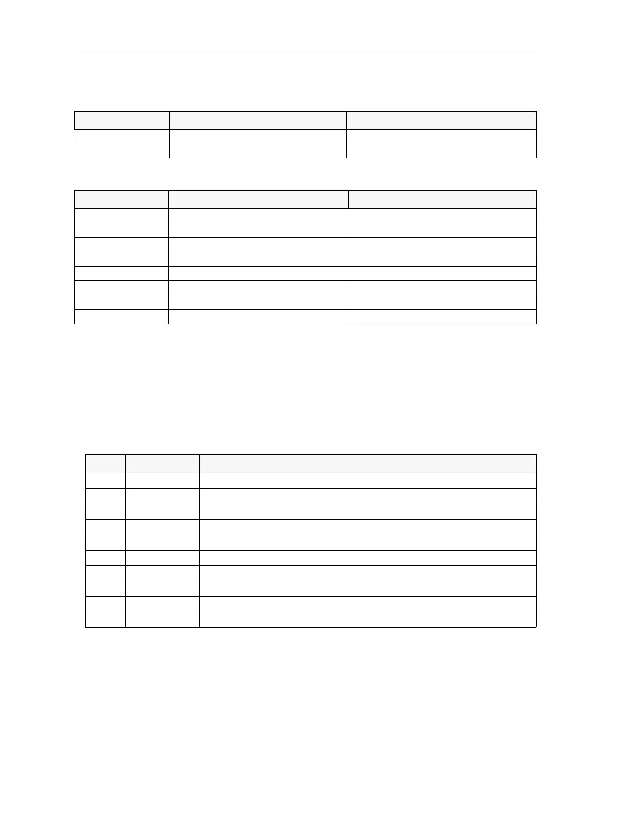
Table 4: Terminal Pinouts for TB1
Line Number Terminating Remote (600) Non-Terminating Remote (6000)
Line 1 = 2-wire JP1 = A & JP4 = N/A JP1 = B & JP4 = N/A
Line 1 = 4-wire JP1 = A & JP4 = A JP1 = B & JP4 = B
Line Number Terminating Remote (600) Non-Terminating Remote (6000)
Line 1 = 2-wire JP1 = A & JP4 = N/A JP1 = B & JP4 = N/A
Line 1 = 4-wire JP1 = A & JP4 = A JP1 = B & JP4 = B
Line 2 = 2-wire JP2 = A & JP3 = N/A JP2 = B & JP3 = N/A
Line 2 = 4-wire JP2 = A & JP3 = A JP2 = B & JP3 = B
Line 3 = 2-wire JP10 = A & JP8 = N/A JP10 = B & JP8 = N/A
Line 3 = 4-wire JP10 = A & JP8 = A JP10 = B & JP8 = B
Line 4 = 2-wire JP7 = A & JP9 = N/A JP7 = B & JP9 = N/A
Line 4 = 4-wire JP7 = A & JP9 = A JP7 = B & JP9 = B
Pin # Label Description
1GND
Ground
2GND
Ground
3 PTT OUT 1
Line 1 PTT Output (Output FET collector releases ground when active)
4 PTT OUT 2
Line 2 PTT Output (Output FET collector releases ground when active)
5 PTT OUT 3
Line 3 PTT Output (Output FET collector releases ground when active)
6 PTT OUT 4
Line 4 PTT Output (Output FET collector releases ground when active)
74W+1
Line 1 4-Wire Audio (+) [RX Audio only]
82W+1
Line 1 2-Wire Audio (+) [TX Audio when used in 4-wire]
92W–1
Line 1 2-Wire Audio (–) [TX Audio when used in 4-wire]
10 4W–1
Line 1 4-Wire Audio (–) [RX Audio only]
 Loading...