EasyManua.ls Logo

ZETRON MAX - User Manual

Default Icon
3 pages
Print Icon
To Next Page IconTo Next Page
Loading...
Call-Taker Position Detail
Notes
Some accessories in this diagram are optional and not required for operation.
The Headset 2 port, Aux In, Speakers 1, 3, and 4 are not used with MAX Call Taking.
A shielded Ethernet patch cable can be used in place of cable 709-0170.
Relay Outputs Out1 and Out2 (normally open) are both active and usable during
MAX CT Operation.
For Additional Information
Media Dock XS Product
Manual
P/N 025-9658
Workstation PC P/N 950-1337
Workstation Touchscreen Laptop P/N 950-1437
Workstation Laptop P/N 950-1394
Aux In
Aux Out
Relay Outputs
| Out1 | Out2 | Out3 | Out4 |
Digital Outputs
| Out1 | Out2 | Out3 | Out4 |
Digital Inputs
| In1 | In2 | In3 | In4/ |
DC PowerSpeaker 1 Speaker 2 Speaker 3 Speaker 4 Desk Mic Headset 1 Headset 2 TRHI USB
Status
Footswitch
Media Dock XS
901-9691 rear view
USB P/N
709-0163
Cable P/N
709-0170
Power
Supply
Headset Jackbox
950-1082 or 950-1077
(rear view shown)
(To front side)
Primary
Zetron Console
To Instant Recall
Recorder
Cable P/N 709-0170-10
Ground
Stud
Power Cable
Strain Relief
P/N 802-0692
P/N 709-0055
Zetron Desktop
Speaker V2
P/N 950-1405
Power Supply
Mains Cable
P/N (various)
Cable
Strain
Relief
Headsets
950-0031, 4-Wire
950-0033, 4-Wire, Noise Cancelling
950-0030, 6-Wire
950-0453, 6-Wire, Wireless
950-0032, 6-Wire, Noise Cancelling w/PTT
950-0454, 6-Wire, Wireless, Noise Cancelling
Headset 2
Not
Supported
Aux In
Not
Supported
System Interconnect for Core Servers
024-0357 K
SIP Phones
950-1350 Polycom VVX 201
950-1351 Polycom VVX 311
950-1352 Polycom VVX 411
950-1353 Polycom VVX 501
950-1354 Polycom IP 5000
950-1355 Polycom VVX Expansion
950-1357 Polycom Power (VVX 201)
950-1358 Polycom VVX D60 Wireless Handset
23" LCD Monitor P/N 802-2311
For Additional Information
Amplified 5W Speaker V2
Product Manual
P/N 025-9585
For Additional Information
Headset Jackbox Product Manual
P/N 025-9632
Speaker 3 and 4
Not
Supported
Speaker 1
Not
Supported
To POE Ports on LAN Switch
To LAN Switch
Telephone Radio
Headset Interface
950-9439
(not shown)
-or-
To Media Dock
XS Relay
Outputs
Console
Position
Light Pole
P/N 950-1237
P/N 950-1438
Connect to
“LAN” port on
SIP phone
Page 1 of 3
Question and Answer IconNeed help?

Do you have a question about the ZETRON MAX and is the answer not in the manual?

Summary

Call-Taker Position Components

Media Dock XS Rear View

Rear view of the Media Dock XS showing output and input ports.

Desktop Speaker and Headset Jackbox

Optional desktop speaker and headset connection interface.

Headset Options

Details on various 4-wire and 6-wire headset models.

Rack Hardware Configuration

Switch and Gateway Options

Available network switches and gateway modules for system integration.

Management Information System Hardware

Hardware component for the Management Information System.

Max Call Taking Server Core

The core server unit for the MAX Call Taking system.

Cabinet AC Power Distribution

Power Strips and UPS Placement

Diagram illustrating power strip and UPS layout in cabinets.

Ethernet I;O Installation Guidelines

Instructions for installing Ethernet I/O modules for gateways.

Overview

This document, "MAX Call Taking System Interconnect for Core Servers," provides a detailed overview of the hardware components and their interconnections for a call-taking system, focusing on the call-taker position and rack configurations. It includes diagrams for the call-taker position detail, typical rack hardware configuration (front view), and cabinet AC power distribution (rear view).

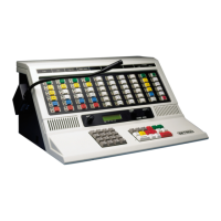
The Call-Taker Position Detail diagram illustrates the individual components at a call-taker's workstation. The central component is the Media Dock XS (901-9691), which serves as the hub for audio, control, and peripheral connections.

Media Dock XS (901-9691):

  • Function: This device acts as the primary interface for the call-taker, managing audio inputs/outputs, relay and digital controls, and peripheral connections. It connects to the workstation PC, SIP phone, headsets, speakers, and an instant recall recorder.
  • Usage Features:
    • Relay Outputs (Out1, Out2, Out3, Out4): Out1 and Out2 are active and usable during MAX CT Operation. Out3 and Out4 are also present. These outputs can be used to control external devices.
    • Digital Outputs (Out1, Out2, Out3, Out4): Provides additional digital control signals.
    • Digital Inputs (In1, In2, In3, In4/Footswitch): Allows for external input, including a footswitch for hands-free operation.
    • Audio Connections:
      • Desk Mic: Input for a desktop microphone.
      • Headset 1: Primary headset connection.
      • Headset 2: Not used with MAX Call Taking.
      • Aux In: Not used with MAX Call Taking.
      • Aux Out: Provides an auxiliary audio output.
      • Speakers (1, 2, 3, 4): Speaker 1 is supported, while Speakers 3 and 4 are not used with MAX Call Taking. Speaker 2 is also supported.
    • USB Port: For connecting USB peripherals.
    • DC Power Input: For powering the Media Dock XS.
    • Ground Stud: For grounding the device.
    • Status Indicators: Visual indicators for device status.
    • Cable Strain Relief: Helps manage and protect connected cables.
  • Important Notes:
    • The Headset 2 port, Aux In, and Speakers 1, 3, and 4 are not used with MAX Call Taking.
    • A shielded Ethernet patch cable can be used in place of cable 709-0170.
    • Relay Outputs Out1 and Out2 (normally open) are both active and usable during MAX CT Operation.
  • Maintenance Features: Refer to the "Media Dock XS Product Manual" (P/N 025-9658) for detailed maintenance information.

Peripherals Connected to Media Dock XS:

  • Console Position Light Pole (P/N 950-1237, 950-1438): Provides visual status indication for the call-taker position.
  • Instant Recall Recorder (P/N 709-0055): Records audio for later review.
  • Zetron Desktop Speaker V2 (P/N 950-1405): An amplified 5W speaker for audio output.
    • Maintenance Features: Refer to the "Amplified 5W Speaker V2 Product Manual" (P/N 025-9585).
  • Telephone Radio Headset Interface (950-9439) or Headset Jackbox (950-1082 or 950-1077): Connects various headsets to the system. The Headset Jackbox is shown in a rear view.
    • Maintenance Features: Refer to the "Headset Jackbox Product Manual" (P/N 025-9632).
  • Headsets: A variety of headsets are supported, including:
    • 950-0031, 4-Wire
    • 950-0033, 4-Wire, Noise Cancelling
    • 950-0030, 6-Wire
    • 950-0453, 6-Wire, Wireless
    • 950-0032, 6-Wire, Noise Cancelling w/PTT
    • 950-0454, 6-Wire, Wireless, Noise Cancelling
  • Power Supply (P/N 802-0692): Provides power to the Media Dock XS.
  • Power Supply Mains Cable (P/N various): Connects the power supply to the mains.
  • USB Cable (P/N 709-0163): Connects the Media Dock XS to the workstation PC.
  • 23" LCD Monitor (P/N 802-2311): Displays the call-taking application.
  • Zetron Console Workstation PC (P/N 950-1337), Workstation Touchscreen Laptop (P/N 950-1437), or Workstation Laptop (P/N 950-1394): The primary computer for the call-taker.
  • SIP Phones: Connects to the LAN switch via its "LAN" port. Supported models include:
    • 950-1350 Polycom VVX 201
    • 950-1351 Polycom VVX 311
    • 950-1352 Polycom VVX 411
    • 950-1353 Polycom VVX 501
    • 950-1354 Polycom IP 5000
    • 950-1355 Polycom VVX Expansion
    • 950-1357 Polycom Power (VVX 201)
    • 950-1358 Polycom VVX D60 Wireless Handset

The Typical Rack Hardware Configuration (Front View) diagram illustrates the arrangement of components within a standard equipment rack, from 1U to 42U.

Rack Components:

  • 2U Audible Stack Light for Core Servers (905-0525): Provides audible and visual alerts for server status.
  • Gateways (1, 2, 3, 4): These devices manage communication interfaces.
    • Gateway Options:
      • 950-1160 FXO Gateway, 12 Port
      • 950-1161 FXO Gateway, 24 Port
      • 950-1182 FXS Gateway, 12 Port
      • 950-1162 CAMA Gateway, 12 Port
      • 950-1164 T1/E1/PRI Gateway
      • 950-1400 Session Border Controller Gateway (Patton SN5501)
      • 950-1401 MAX Call Taking T1/E1/PRI Gateway
  • Switches (A, B): Network switches for connecting devices.
    • Switch Options:
      • 950-1284 24-Port, (24-POE) Managed Gigabit Rackmount Switch
      • 950-1286 48-Port, (48-POE) Managed Gigabit Rackmount Switch
      • 950-1459 24-Port, (24-POE) Managed Gigabit Rackmount Switch
      • 950-1460 48-Port, (48-POE) Managed Gigabit Rackmount Switch
  • Cable Manager (802-0174): Organizes and routes cables within the rack.
  • Power Strips (A, B) (802-0370): Provides power distribution to rack-mounted equipment.
  • 1U Blanking Plates (415-0484-1): Fills unused rack spaces for improved airflow and aesthetics.
  • MAX Call Taking Server Core (905-0526): The core servers for the call-taking system. There are four core servers (1, 2, 3, 4).
  • 802-0330 UPS (Uninterruptible Power Supply): Provides backup power to ensure continuous operation during power outages. Two UPS units are shown, likely for redundancy.
  • Management Information System (Hardware 683-0500) (905-0477): An optional component for system management and monitoring.

Cabinet AC Power Distribution Diagram (Rear View) illustrates the power connections within the rack.

Power Distribution Features:

  • Each power strip has 6 outlets on the front and 6 outlets on the back, totaling 24 devices that can be powered.
  • High Availability: To ensure high availability, devices should be connected with redundant power paths:
    • Connect device's blue AC line cord to the blue power strip.
    • Connect device's red AC line cord to the red power strip.
  • 802-1218 Ethernet I/O (POE) Installation: Gateways are omitted for clarity in this diagram.
  • 802-1218: This appears to be a network device, possibly a PoE switch or injector.
  • 950-1399 (Optional 3 PLCS): Likely a mounting bracket or accessory.
  • 802-0213 19' Rackmount DIN Rail Mounting Kit: Used for mounting DIN rail compatible devices in a 19-inch rack.

Additional Information and Manuals:

The document references several manuals for further details on operation, administration, and maintenance:

  • 025-9656 Console Operation Manual
  • 025-9672 Administration Manual
  • 025-9679 System Technical Overview Manual
  • 025-9697 Map Viewer Manual
  • 025-9697-1 MAX CAD Map Viewer Manual
  • 025-9706 System Configuration and Maintenance Manual
  • 025-9707 Installation Manual
  • 025-9718 Management Information System (MIS) S/W Installation Manual

This comprehensive set of diagrams and references provides a clear understanding of the MAX Call Taking System's hardware architecture, from the individual call-taker's workstation to the core server rack, emphasizing connectivity, power distribution, and options for customization and redundancy.

ZETRON MAX Specifications

General IconGeneral
BrandZETRON
ModelMAX
CategoryControl Systems
LanguageEnglish

Related product manuals