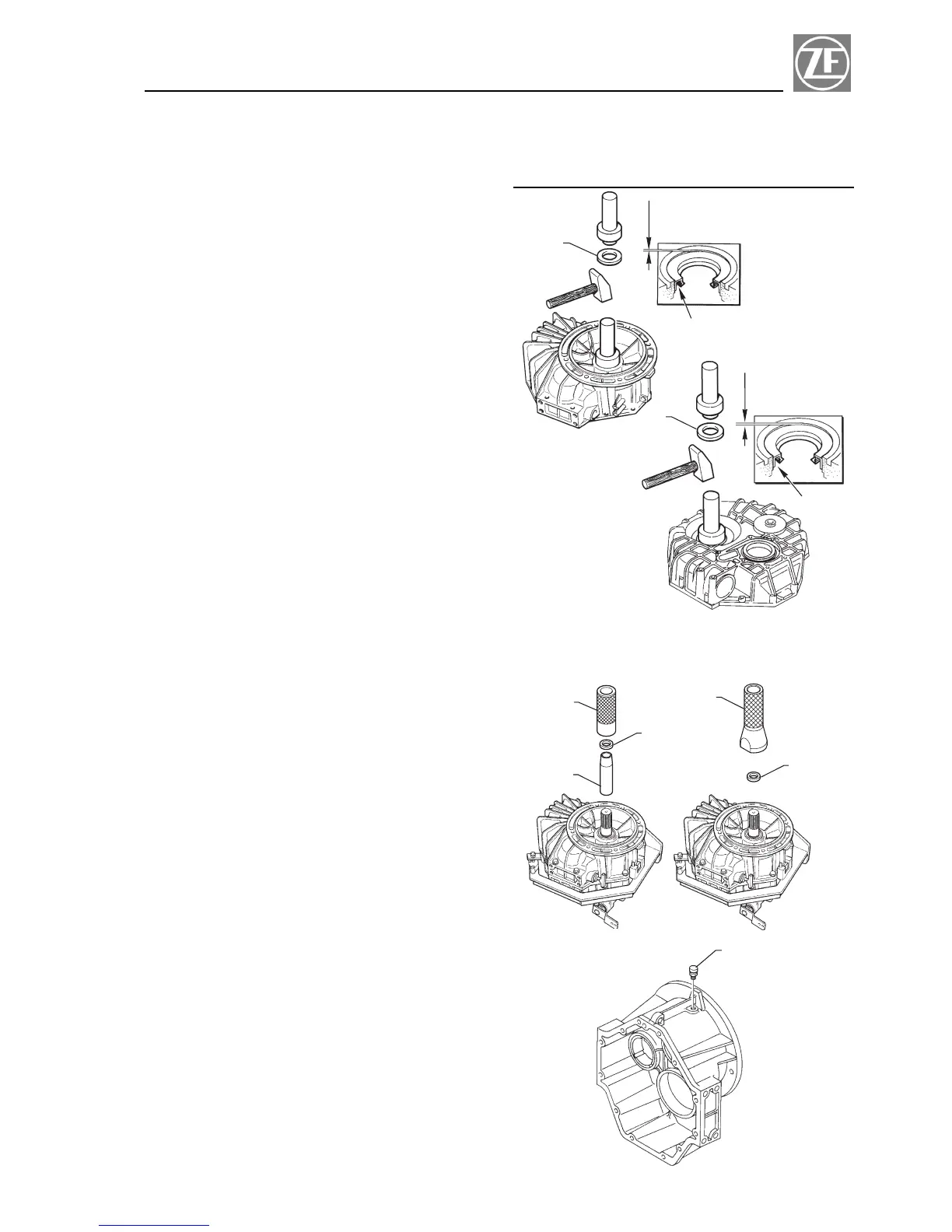
4.4.3 Assembling input shaft seal
Apply thin coat of Loctite 574 on periphery of new radial
shaft seal rings (item 1, Fig. 4-3a and Fig. 4-3b) and
grease lips with KLUEBER STABURAGS NBU 30.
Put it onto the mounting mandrel.
Drive shaft seal uniformly into the housing by tapping
slightly onto the mounting mandrel.
NOTE
The sealing lip (A) on the shaft seal should point into
the inside of the housing. The radial shaft seal must
be adjusted so that the sealing lip runs on the
grounded surface of the shaft.
ALTERNATIVELY (Fig. 4-3c):
For models ZF 63 A - ZF 63 - ZF 80 A - ZF 80-1 A
.
Smear loctite 574 on the outside diameter of the in-
put shaft seal using a roller.
.
Lubricate the inside lip with Kluber Staburags
NBU30 grease.
.
Insert the input shaft seal (item 2) into input shaft
using the appropriate bushing p/n 20.0012.01 (item 1).
.
Use mandrel p/n 20.0012.02 (item 3) to position the
input shaft seal in the correct way.
For model ZF 85 A
.
Smear loctite 574 on the outside diameter of the in-
put shaft seal using a roller.
.
Lubricate the inside lip with Kluber Staburags
NBU30 grease.
.
Insert the input shaft seal (item 2) into input shaft using
the appropriate mandrel p/n 20.1072.01 (item 1).
.
Position the input shaft seal in the correct way.
4.4.4 Mounting the breather filter
Due to the taper thread, the breather (item 1, Fig. 4-4)
need not to be coated with Loctite 574.
Tighten carefully during assembly (hand-tight).
Cheek leakage during a later test run. Retighten
slightly if it leaks.
21
Repair Manual and Spare Parts List Section 4
1
1 mm
A
FIG. 4 - 3a
1
1 mm
A
FIG. 4 - 3b
1
2
3
ZF 63 - ZF 63 A
ZF 80 A - ZF 80-1 A
1
FIG. 4 - 4
1
2
FIG. 4 - 3c
ZF 85 A
 Loading...