EasyManua.ls Logo

ZIEHL MSF 220 SE User Manual

ZIEHL MSF 220 SE
4 pages
To Next Page IconTo Next Page
Page #1 background imageLoading...
Page #1 background image
(datum / name): 10.12.08 Su/Fz Z. Nr.: 1004 0710.2
Page 1 von 4 Type: MSF 220 SE
ZIEHL industrie-elektronik GmbH + Co KG, Daimlerstr.13, D-74523 Schwäbisch Hall, Tel.: +49 791 504-0, Fax: -56, e-mail: info@ziehl.de
Operating manual
MSF 220 SE
Application
The PTC-resistor trip device MSF 220 SE monitors the winding temperature of machines and
equipment. Signals, that can be used as ”early warning" or ”malfunction" (switching-off), are
transmitted as soon as the admissible limit temperature is exceeded.
Two PTC-circuits can be connected to this unit. The integrated rise-delay time ensures a
reliable mains voltage build-up.
Function
* 2 PTC resistor circuits, 1 to 6 PTC each (max. cold resistance of circuit 1500 each)
* p
otential-free contact for alarm 1
* potential-free contact for alarm 2
* voltage of pin 3 is connectet to pin 1 with a time delay of 2 sec., replacing an additional
timing relay.
* alarm 3 for check of relay K3
* LED´s signal state of relays K1 and K2
* relay K3 picks up time-delayed
Note
Thanks to the delayed switching-on of the error message (approx. 2 s) after the switching-on,
this device is especially suitable where an auxiliary voltage is not available and the secondary
voltage of the monitored transformer is being used. The MSF-200 SE can furthermore be used
advantageously when combining it with operating current releases. For additional devices, the
control voltage is available at terminal 1 time-delayed. In case of a breakdown of the supply
voltage, the control voltage is available at terminal 7 and can be used as a message.
(Attention! This message will also be given for approx. 2 s. after switching-on.)
Functional description
PTC-circuits in closed-circuit current principle. When the closed-circuit current flows, both
output relays K1, K2 are picked up. Approx. 2 sec. after switching on supply power, relay K3
picks up time-delayed, closing the contact circuits at terminals 31, 14 and 31, 24. As soon as
the temperature of the early warning has been reached, relay K1 releases (terminal 31, 12
closed), the alarm 1 is given. If the temperature of malfunction is reached, also relay K2
releases (terminal 31, 22 closed). This alarm 2 can be used to switch off the equipment. If the
temperature drops to approx. 5 °C below the temperature of malfunction or early warning, the
relays K1 and K2 resp. are switched on again.
MINIPAN
®
digital panel meters, temperature
-
and mains controlling,
special purpose instruments for customer requirements www.ziehl.com
- Archive document
www.ziehl.de
Question and Answer IconNeed help?

Do you have a question about the ZIEHL MSF 220 SE and is the answer not in the manual?

ZIEHL MSF 220 SE Specifications

General IconGeneral
Frequency50/60 Hz
MountingDIN Rail
Operating Temperature-20°C to +60°C
Protection ClassIP20
OutputRelay

Summary

MSF 220 SE Overview

Application

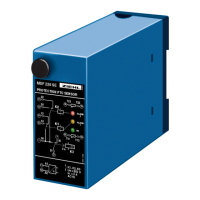
Explains the purpose of the PTC-resistor trip device MSF 220 SE for monitoring machine temperatures and transmitting signals.

Key Functions

Details the device's features including PTC circuits, potential-free contacts, and time-delayed relays.

Functional Description

Describes the operation of PTC circuits, relays K1, K2, and K3 based on temperature thresholds and switching delays.

Technical Data

PTC-Resistor Connection

Specifies the PTC resistor circuit configuration, cut-out/reclosing points, and sensor voltage limits.

Relay Output Specifications

Details the switching voltage, current, power, and contact ratings of the device's relays.

Testing Conditions

Outlines the standards and conditions under which the device's performance is tested, including insulation and impulse voltage.

Installation and Operation

Wiring and Initial Setup

Guides on wiring the device, connecting wires as per scheme, and initial power-up procedures.

Operational Sequence

Explains the step-by-step behavior of relays K1, K2, and K3 upon power application and temperature changes.

Troubleshooting

Provides solutions for common issues like relays not switching on or LEDs lighting up continuously.

Wiring and Design Details

Wiring Scheme

Illustrates the electrical connections and terminal assignments for the MSF 220 SE device.

Physical Design

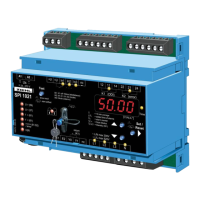
Presents the mechanical dimensions, mounting features, and overall physical layout of the MSF 220 SE unit.

Related product manuals