/ 8 www.ziehl.de
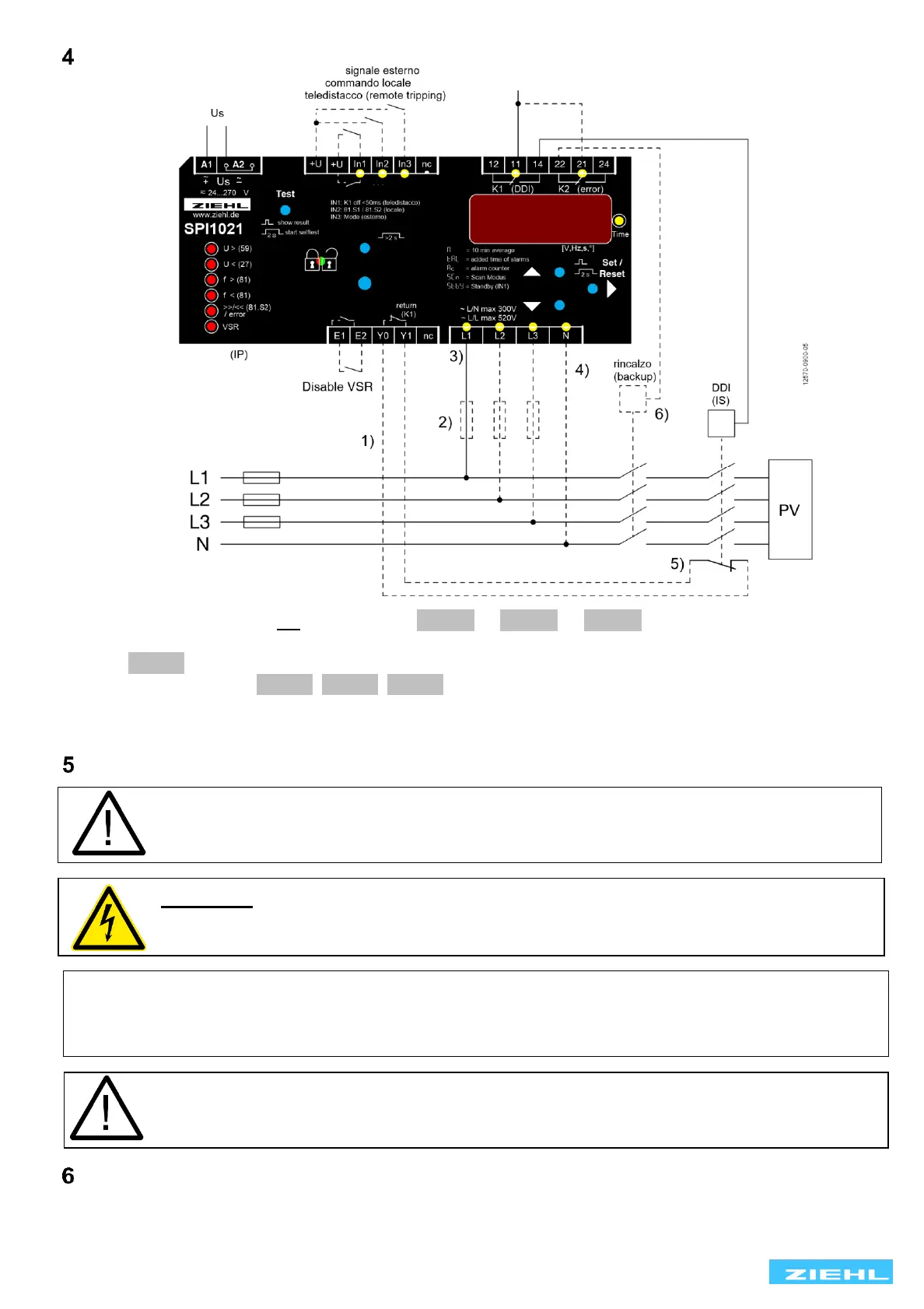
Connection diagram
1) Feedback contacts not connected set 8rel .8 → 8trel.8 → 8 off.8
2) Fuses only when line protection necessary, e.g. 3x16A
3) 8Pr 38 Phase connect to L1, L2 and L3 are not connected
4) N connected set 8Pr 18, 8Pr 38, 8Pr 48
5) NC- or NO-contacts can be connected, automatic detection when switching on
6) must be connected for plants ≥ 20kW
Important information
A marked switch and a protective device must be provided in the supply line in the
vicinity of the device (easily accessible) as a disconnecting element
(rated current ≤ 6A).
WARNING Hazards electrical voltage!
Can lead to an electric shock and burns.
Disconnect and de-energize before working on the system and the device.
Comply with the maximum permissible temperature when installing in a switch cabinet. Ensure
sufficient clearance to other devices or heat sources. If cooling is inhibited, e.g., through close
proximity to devices with increased surface temperature or interference with the cooling-air current,
the permissible ambient temperature is decreased.
Caution!
Before you apply mains voltage to the device, make sure that the permissible control
voltage Us on the side rating plate matches the mains voltage connected to the device!
Assembly
The device can be mounted:
• Distribution panel or control panel on 35 mm rail according to EN 60715
 Loading...