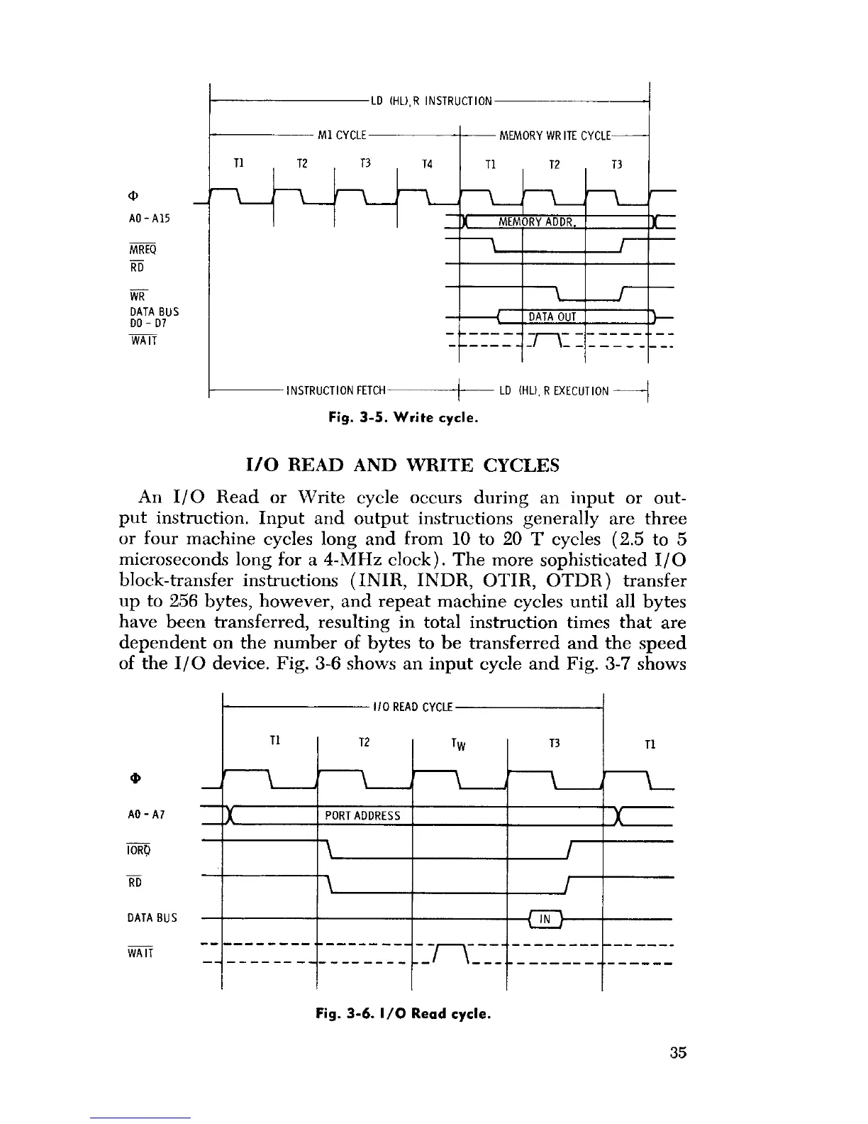
LD (HL),R INSTRUCTION
T1 T2
m
AO-A15
MREQ
RD
WR
DATA BUS
DO - D7
WAIT
M1 CYCLE
T3 T4
MEMORY ADDR.
MEMORY WR
ITE CYCLE
T1 T2 T3
A
DATA OUT
INSTRUCTION FETCH
LD (HU, R EXECUTION
I/O READ AND WRITE CYCLES
An I/O Read or Write cycle occurs during an input or out-
put instruction. Input and output instructions generally are three
or four machine cycles long and from 10 to 20 T cycles (2.5 to 5
microseconds long for a 4-MHz clock). The more sophisticated I/O
block-transfer instructions (INIR, INDR, OTIR, OTDR) transfer
up to 256 bytes, however, and repeat machine cycles until all bytes
have been transferred, resulting in total instruction times that are
dependent on the number of bytes to be transferred and the speed
of the I/O device. Fig. 3-6 shows an input cycle and Fig. 3-7 shows
CYCLE
RD
DATA BUS
WAIT
TI
Fig. 3-5
. Write cycle.
T2 I TW
PORT ADDRESS
Fig. 3
-
6. 1/0 Read cycle.
T3
IN
Ti
i
J
f
35
 Loading...