RFSH lines by enabling the input signal BUSRQ. Normally, the
reason for this would be to allow an external device controller to
communicate directly with external memory to transfer data be-
tween high-speed I/O devices and memory without CPU interfer-
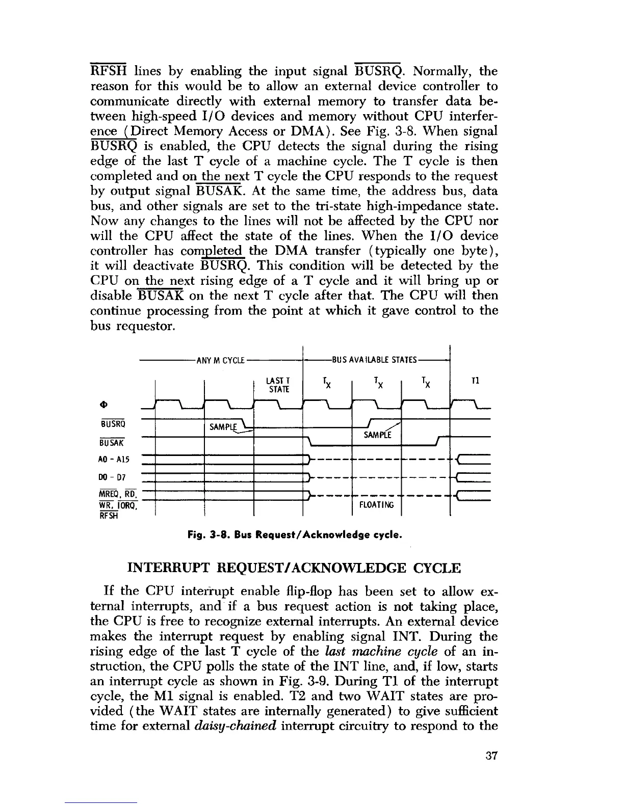
ence Direct Memory Access or DMA). See Fig. 3-8. When signal
BUSRQ is enabled, the CPU detects the signal during the rising
edge of the last T cycle of a machine cycle. The T cycle is then
completed and on the next T cycle the CPU responds to the request
by output signal BUSAK. At the same time, the address bus, data
bus, and other signals are set to the tri-state high-impedance state.
Now any changes to the lines will not be affected by the CPU nor
will the CPU affect the state of the lines. When the I/O device
controller has com l
p eted the DMA transfer (typically one byte),
it will deactivate BUSRQ. This condition will be detected by the
CPU on the next rising edge of a T cycle and it will bring up or
disable BUSAK on the next T cycle after that. The CPU will then
continue processing from the point at which it gave control to the
bus requestor.
ANY M CYCLE
4,
BUSRQ
BUSAK
AO-A15
DO - D7
BUS AVAILABLE STATES
Tx T1
LAST T Tx Tx
STATE
SAMPLE /
SAMPLE
MREQ.
RD. _ +____ +=
WE FLOATIN
IORQ,G
RFSH
Fig. 3-8
.
Bus Request
/Acknowledge cycle.
INTERRUPT REQUEST
/
ACKNOWLEDGE CYCLE
If the CPU interrupt enable flip-flop has been set to allow ex-
ternal interrupts
,
and if a bus request action is not taking place,
the CPU
is free to recognize external interrupts
.
An external device
makes the interrupt request by enabling signal INT. During the
rising edge of the last T cycle of the
last machine cycle
of an in-
struction, the CPU polls the state of the INT line, and
,
if low, starts
an interrupt cycle as shown in Fig. 3-9. During TI of the interrupt
cycle,
the M1 signal is enabled
.
T2 and two
WAIT
states are pro-
vided
(the WAIT
states are internally generated) to give sufficient
time for external
daisy
-
chained
interrupt circuitry to respond to the
37
 Loading...