Function-Decoders MX681, MX685, MX686, MX687, MX688 Page 15
Special effects
American lighting effects
as well as others such
as uncoupler, smoke
generator and more
on
function output F0 (front
headlight)
Effects can be further
adjusted and modified
with
CVs #62 - 63
and
CV #115, #116
(for uncoupler).
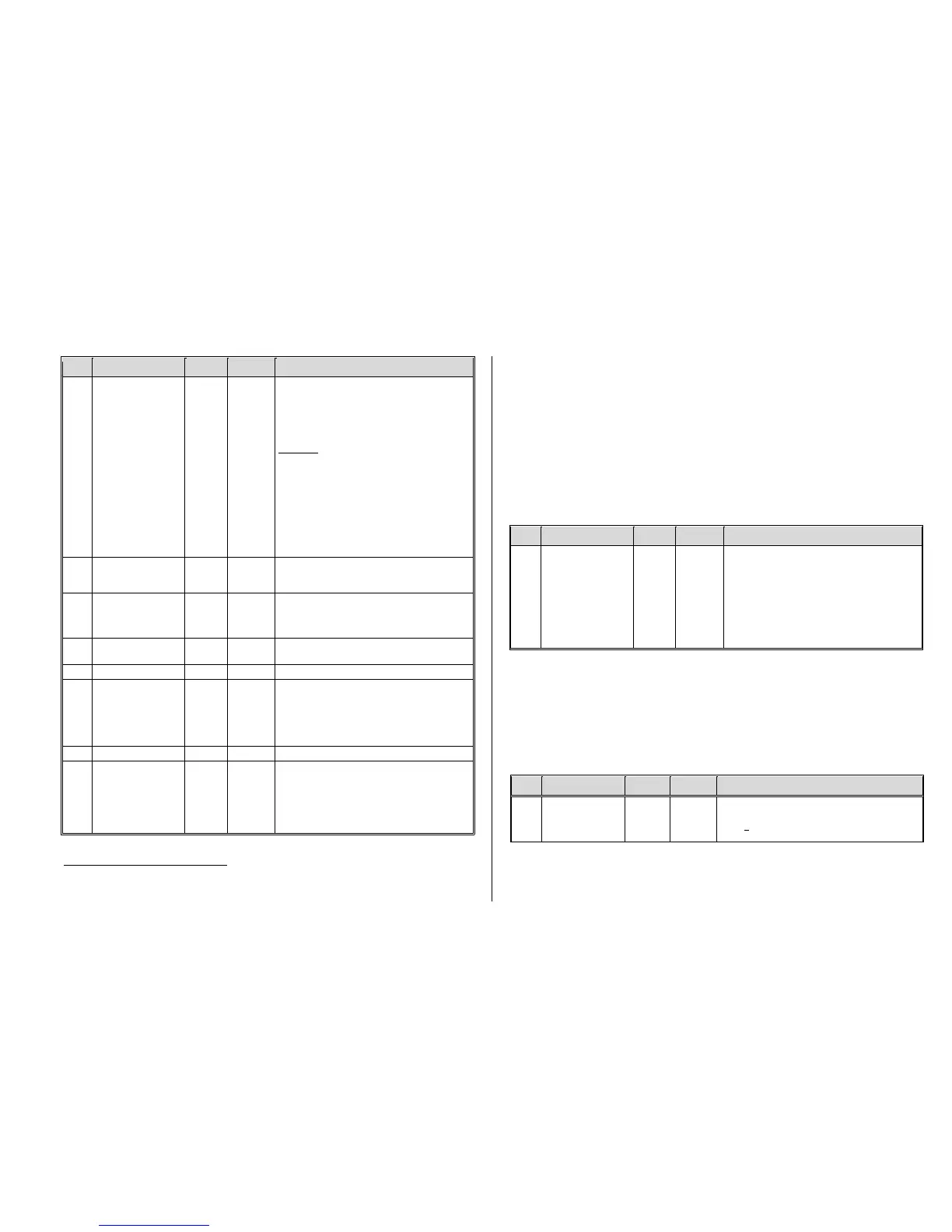
Bits 1, 0 = 00: bidirectional (active in both directions)
= 01: only active in forward direction
= 10: only active in reverse direction
ATTENTION in case of CV #125 and #126: change
CV’s #33, 34.... if direction is wrong!
Bits 7, 6, 5, 4, 3, 2 = effect-code
EXAMPLES
You want : Program CV #125 to: Mars light
forward only - 00000101 = 5
Gyralite independent of direction - 00011100 = 28
Ditch type 1 left, only forward - 00100101 = 37
Uncoupler - 00110000 = 48
Soft start of output - 00110100 = 52
Automatic stop light - 00111000 = 56
Automatic cab light OFF - 00111100 = 60
Auto. smoke OFF after 5 min – 01000000 = 64
Auto. smoke OFF after 10 min – 01000100 = 68
Speed/load depen. smoke - 01001000 = 72
Speed/load depen. diesel smoke - 01010000 = 80
Special effects for
rear headlight
(default F0 reverse)
Special effects for
FO1, FO2, FO3,
FO4, FO5, FO6
See CV #125 for details
#127 FO1 #128 FO2
#129 FO3 #130 FO4
#131 FO5 #132 FO6
Special effects for
FO7, FO8
See CV #125 for details
#159 FO7 #160 FO8
Change of minimum dimming value
Light effects
modifications
or
Stop light OFF delay
Tens digit: sets cycle time (0 - 9, default 5), or start-up
time during soft start with 001101 (0 - 0,9s)
Ones digit: OFF delay time (range: 0 – 25 sec.).
For stop light OFF delay (001110xx in CV #125, 126
or 127): Time in tenths of a second the stop lights re-
main ON after the street car comes to a full stop.
Ditch light OFF time modification
Automatic
smoke generator
shut-down
For special effect codes “010010xx” or “010100xx”
(smoke generator): Overheat protection: turns OFF
from ½ min – about 2 hours.
= 0: Won’t turn off automatically.
= 1 … 252: Switches off automatically after 25 sec-
onds/unit. Maximum time therefore is about 6300 sec.
105 min.
Note to ditch lights: Ditch lights are only active when headlights and function F2 (#3 on Zimo cab) are on, which is prototypical for North American railroads. The
ditch lights will only be working if the applicable bits in CV #33 and 34 are on (the definition in CV #125 - 128 in itself is not enough but a necessary addition).
Example: If ditch lights are defined for F1 and F2, the bits #2 and 3 in CV #33 and 34 have to be set accordingly (i.e. CV # 33 = 13 (00001101), CV #34 = 14
(00001110).
3.15 Configuration of Electric Uncouplers
“System KROIS” and “System ROCO”
When one or two of the function outputs FO1…FO6 (but not FO7 or FO8) are assigned to the uncou-
pler function (CV #127 for FO1 etc.), the control of the couplers as well as the entire uncoupling pro-
cess is defined by the settings in
CV #115 and CV #116.
These CVs limit the pull-in time (to prevent overheating), define a hold-in voltage if required (i.e. Sys-
tem “Roco”) as well as the automated coupler unloading and train disengagement.
It is recommended to use the following settings for the Krois system: CV #115 = 60, 70 or 80; these
settings will limit the pull-in voltage (full track power) to 2, 3 or 4 seconds respectively. A hold-in voltage
is not required for the Krois coupler and the ones digit can therefore remain at “0”.
Uncoupler control
“Pull-in” time
and
“hold” voltage
or use
CV # 115
for an alternative second
dim value
Uncoupler function is only active if “uncoupler” is se-
lected (value 48) in one of the CV’s #125…132:
Tens digit (0 – 9): Time in seconds the coupler re-
ceives full voltage (pull-in time):
Value: 0 1 2 3 4 5 6 7 8 9
seconds: 0 0,1 0,2 0,4 0,8 1 2 3 4 5
Ones digit (0 to 9): hold-in power in percent of track
voltage, 0 - 90%. Applied after the pull-in time elapsed
(necessary for ROCO coupler, not needed for KROIS
coupler).
3.16 SUSI-Interface and Logic-Level Output
All decoders described in this manual (except for the MX681) have outputs that can either be used as
a SUSI interface, as logic level outputs or for servo control. These outputs are available at solder
pads or on the decoder plug (MTC or PluX), see the various decoder drawings starting on page 3.
These outputs are active by default as SUSI interface. They can be switched for the alternative appli-
cations with CV #124 (Bit 7) or CV’s #181 and #182 (see next chapter “Servo configuration).
Shunting key
functions:
Changing SUSI
outputs
Bits 0 - 4, 6: Shunting key selection and
HALF-SPEED ACTIVATON
Bit 7 = 0: SUSI active instead of normal functions
= 1: Normal function outputs instead of SUSI