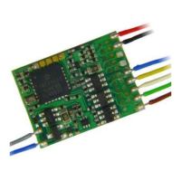
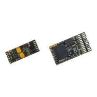
Page 8 Function-Decoders MX681, MX685, MX686, MX687, MX688
Alternate Mode
Function Status
F1- F8
Select the functions that should be ON during analog
operation.
Bit 0 = 0: F1 OFF in analog mode
= 1: …ON…
Bit 1 = 0: F2 OFF in analog mode
= 1: …ON…
………. F3, F4, F5, F6, F7
Bit 7 = 0: F8 OFF in analog mode
= 1: …ON…
Alternate Mode
Function. Status
F0, F9-F12
and
acceleration,
deceleration and motor
control in analog
67,
that is
Bit
0, 1, 6 = 1
Select the functions that should be ON during analog
operation.
Bit 0 = 0: F0 (forward) OFF in analog mode
= 1: …ON…
Bit 1 = 0: F0 (reverse) OFF in analog mode
= 1: …ON…
Bit 2 = 0: F9 OFF in analog mode
= 1: …ON…
………. F10, F11
Bit 5 = 0: F12 OFF in analog mode
= 1: …ON…
Bit 6 = 0: Analog operation with momentum as per
CVs #3 + 4; often needed for sound
= 1: Analog operation without momentum from
CVs #3 + 4; immediate response to track
voltage similar to classic analog control.
Bit 7 = 0: Analog operation without motor regulation.
= 1: Analog operation with motor regulation.
3.7 “Virtual” motor control and momentum
Even though function decoders don’t have an actual motor output, they can still be programmed with pa-
rameters for “virtual motor control”, in order to synchronize the actions of the function decoder with the
loco decoder, provided the first or second address of the function decoder is identical with the loco de-
coders. This is especially important during acceleration or deceleration, for example, when activating the
direction key without first stopping the train. It makes sense to use the same settings in these CV's as are
used in the locomotive decoder.
However, the 28-speed point curve is not available, only the three-point curve, because the relevant CV
numbers are used for the second address. For this reason, Bit 4 in CV #29 is also not available. And of
course, CV settings that relate to motor feedback are unnecessary.
For many applications though, the motor control CVs are not important
in function decoders. Setting CV #3 and #4 to match the CVs
of the loco decoder is sufficient.
Internal speed step (1 … 255) applied as
lowest external speed step (= speed step 1)
(applies to 14, 28, or 128 speed step modes)
= 1: lowest possible speed
Internal speed step (1 … 255) applied as
highest external speed step
(14, 25 or 128, depending on the speed step mode
selected in CV # 29, Bit 1)
= 1 (same as 255): fastest speed possible.
1,
¼ to ½
of the
value in
CV #5
Internal speed step (1 … 255) applied as
medium external speed step (that is, speed step 7,
14 or 63 depending on the speed step mode selected
in CV #29, Bit 1)
”1" = default curve (Medium speed is set to one third of
top speed, i.e., if CV #5 = 255 the curve is the same as
if CV #6 would be programmed to 85)
The speed curve resulting from CV #2, 5 and 6 is auto-
matically smoothed out to prevent kinks.
The value multiplied by 0.9 equals acceleration time in
seconds from stop to full speed.
The effective default value for sound decoders is usual-
ly not the value given here, but is determined by the
loaded sound project.
The value multiplied by 0.9 equals deceleration time in
seconds from full speed to a complete stop.
The effective default value for sound decoders is usual-
ly not the value given here, but is determined by the
loaded sound project.
To temporarily increases the acceleration rate to a new
load or when used in a consist.
Bit 0-6: entered value increases or decreases
acceleration time in CV #3.
Bit 7 = 0: adds above value to CV #3.
= 1: subtracts above value from CV #3.
As above, but for deceleration and therefore CV #4.
Acceleration time (momentum) can be stretched in the
lower speed range:
Tens digit: Percentage of speed range to be
included (0 to 90%).
Ones digit: Exponential curve (0 to 9).
EXAMPLE:
CV #121 = 11, 23 or 25 are typical initial test values.
Deceleration time (momentum) can be stretched in the
lower speed range:
Tens digit: Percentage of speed range to be
included (0 to 90%).