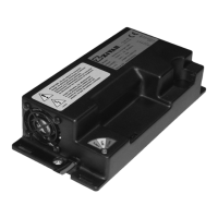
SG6 CAN Bus Interface English
D01596-03 11
Alarms
(display version)
When an alarm situation stopping the charge occurs, the display shows one of the information below according failure detected:
<A> <alarm code identified with a 2 digits code>
Alarm table list here following:
CODE ALARM TYPE DESCRIPTION STOP
A01 LOGIC FAILURE #1 Trouble on current detection YES
A02 CAN BUS KO Trouble on CAN communication NO
A03 WATCHDOG Logic board mis-working YES
A05 HIGH TEMPERATURE BATTERY Battery over temperature (>55°C) Temporary
A07 OVERCURRENT Over current Temporary
A08 HIGH TEMPERATURE Battery charter high temperature YES
A11 TIME OUT End of Phase 1 due to timeout YES
A14 SHORT OUPUT Short circuit ar the output stage YES
A16 LOGIC FAILURE #2 Voltage sag Temporary
A20 EEPROM KO Problem in EEPROM communication YES
A21 FLASH CHECKSUM Microcontroller flash corrupted YES
Notes:
A05: The charge restarts once the battery temperature reaches a value lower than 45°C.
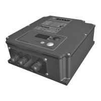
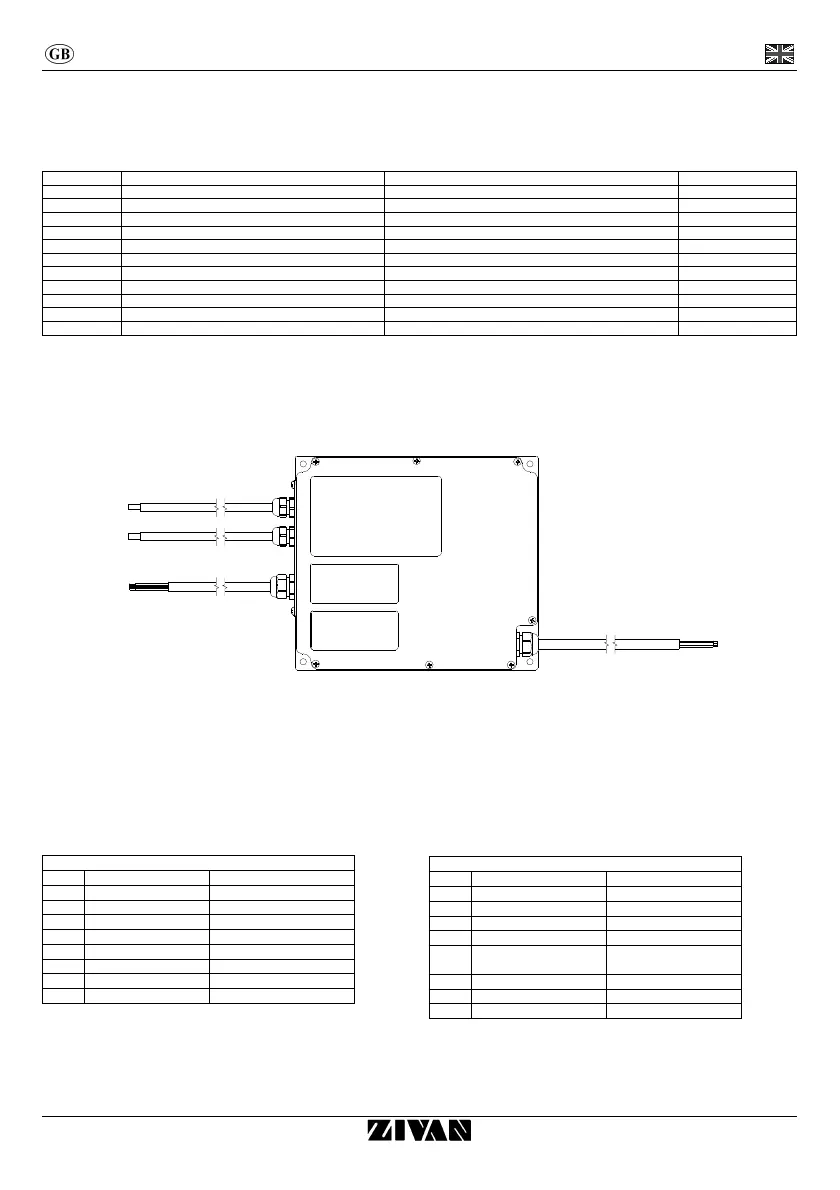
Connections
OUT
AUX
IN
Input and output cables
INPUT: multiwires cable 3x2.5mm².
OUTPUT (currents up to 25A): Flex cable 6mm² (red wire for the positive pole, black wire for the negative).
OUTPUT (currents up to 50A): Flex cable 10mm² (red wire for the positive pole, black wire for the negative).
Auxiliary inputs and outputs cable
Connector MICRO-FIT 8 outs MA
PIN Wire colour Description
1 Black AUX NC
2 White / Yellow AUX COM
3 Pink GND
4 Grey / Pink NPT100
5 Violet AUX NO
6 - N.C.
7 Grey Digital Input
8 Blue / Red PPT100
Connector MICRO-FIT 8 outs FE
PIN Wire colour Description
1 Red CAN POS
2 Blue CAN NEG
3 Yellow CAN H
4 Green CAN L
5 White / Green
CAN HT (120Ω già
connesso al CAN H)
6 Brown / Green CAN L
7 White GND
8 Brown +12V